Automatic motor driven in-line piston pump lubricator

a technology of piston pump and automatic motor, which is applied in the direction of lubricating pump, engine lubrication, engine components, etc., can solve the problems of substantial time elapse, damage accordingly, and danger of overlubrication, which can also be damaging

Active Publication Date: 2009-05-28
STEPHANIA HLDG
View PDF55 Cites 18 Cited by
  • Summary
  • Abstract
  • Description
  • Claims
  • Application Information

AI Technical Summary

Problems solved by technology

In some devices, if the back pressure is too high, or the temperature is too low, substantial time may elapse before the lubricant reaches the machinery intended to be lubricated, such as a bearing, and the latter may then become starved for lubricant and suffer damage accordingly.
Conversely, under high temperature conditions there is the opposite danger of overlubricating which can also be damaging.

Method used


Image

  • Automatic motor driven in-line piston pump lubricator
  • Automatic motor driven in-line piston pump lubricator
  • Automatic motor driven in-line piston pump lubricator

Examples


Embodiment Construction

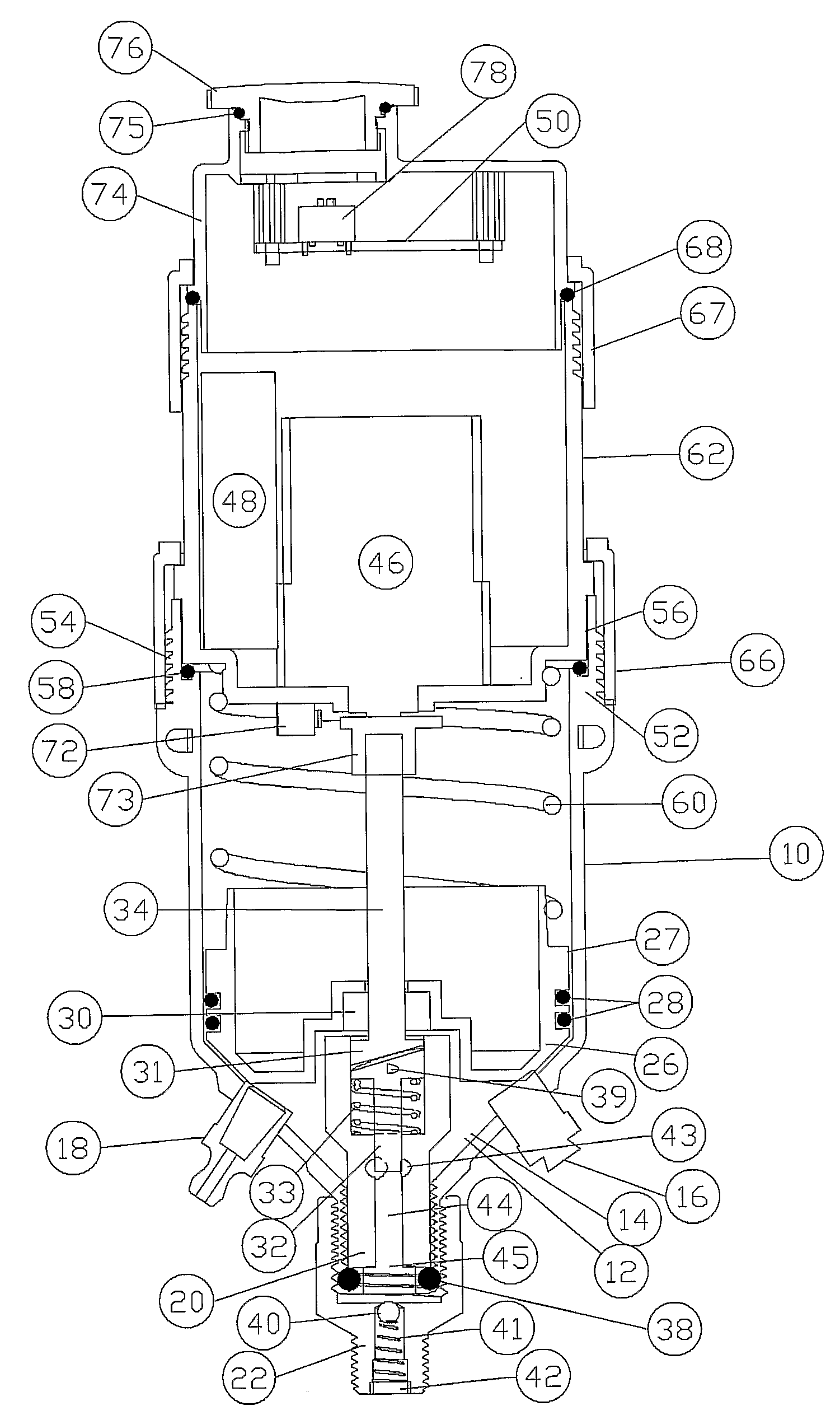
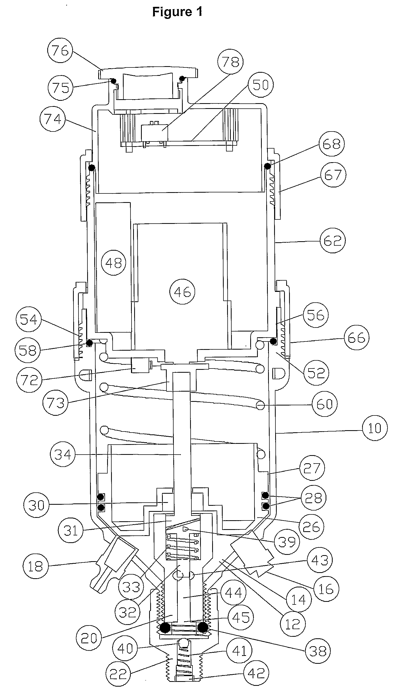
[0014]In some aspects, the invention comprises a portable device for single point or multiple point lubrication that includes a container having an outlet to be connected to the lubricating system of the machinery; a cam-pump lubricant dispensing mechanism between the container and the outlet. In selected embodiments, such a device may be adapted to produce relatively high pressure using a relatively small DC powered motor using a relatively small current draw (e.g. 0.500 amperes at 6 volts DC for 1200 psi). Selected embodiments may be made to be customer refillable using ordinary grease guns. Exemplary embodiments are illustrated herein, and described below, on the understanding that alternative embodiments may be implemented in keeping with the general scope of the invention as claimed.

[0015]FIG. 1 depicts in vertical elevation a cross-sectional drawing of a lubricator 10 constructed within a cylindrical, elongated chamber 12. The lower portion of chamber 12 is generally V-shaped ...


PUM


Abstract

In various embodiments, the invention provides a lubricator comprising a housing defining a main lubricant chamber adapted to contain a fluid lubricant. A piston pump in fluid communication with the main lubricant chamber may be adapted to be driven to discharge the lubricant from a pump chamber through a lubricant outlet in the housing. A check valve may be mounted on the lubricant outlet, to check the discharge of lubricant from the lubricator. The lubricator may include a motor having a drive shaft adapted to rotate a swash plate to act as a cam to drive reciprocating motion of the pump piston in the pump chamber. The drive shaft may be in axial alignment with the piston, the swash plate being set obliquely on the drive shaft to revolve when the motor is activated to give reciprocating motion to the piston in a direction parallel to the drive shaft. The piston may be biased in the pump chamber against the swash plate, so that the swash plate rides on the piston.

Description

FIELD OF THE INVENTION[0001]The invention relates to methods and apparatus for automatic lubrication of machinery, particularly bearings, that have fittings thereon adapted to receive a quantity of grease or similar lubricant, and more specifically to methods and apparatus that involve a selectable scheduling of lubrication and the active transport of a lubricant, especially by a cam-pump device, that will then inject such lubricant through such fittings into particular machinery that has been connected thereto.BACKGROUND OF THE INVENTION[0002]Lubricators that utilize compressed air, compressed springs, motor driven jack screws, augers or a gas generating cartridge as a driving force to eject lubricant into a machine are known in the prior art. For example, U.S. Pat. No. 4,023,648 to Orlitzky et al. describes a lubricant applicator that electrolytically generates a gas as a driving means to force lubricant out of a chamber into a bearing fitting. U.S. Pat. No. 4,671,386 to Orlitzky ...

Claims


Application Information

Patent Timeline
Patent Type & Authority Applications(United States)
IPC IPC(8): F16N13/14F16N11/08F16N13/02F16N27/00
CPCF16N13/14F16N13/02
Inventor ORLITZKY, ANTONORLITZKY, STEPHANSHEREMETA, DANNY
Owner STEPHANIA HLDG
Why Eureka
Try Eureka