

Reflow furnace
- Summary
- Abstract
- Description
- Claims
- Application Information
AI Technical Summary
Benefits of technology
Problems solved by technology
Method used
Image

Examples
Embodiment Construction
[0060]Below, a reflow furnace according to the present invention will be explained based on the drawings.
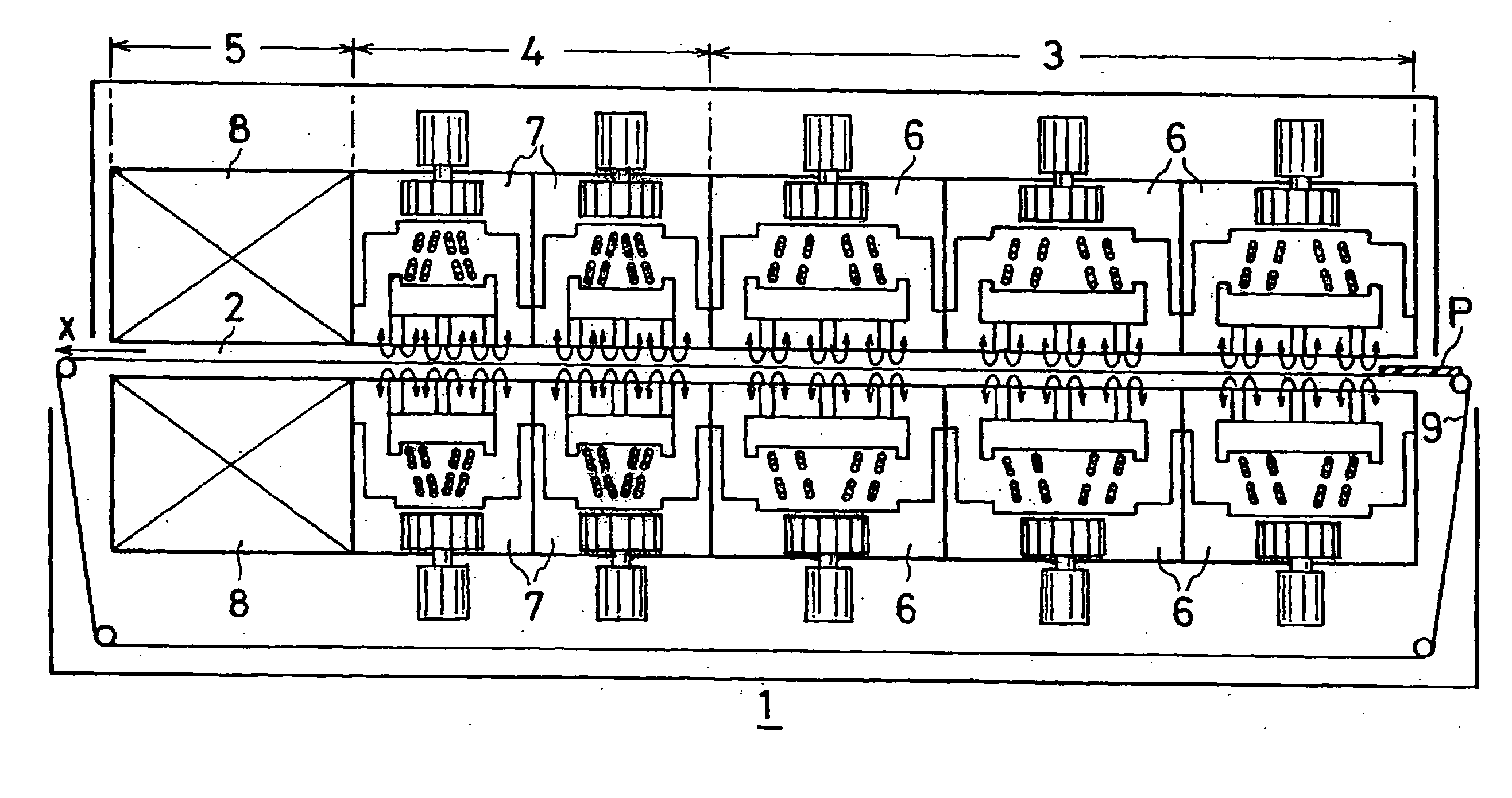
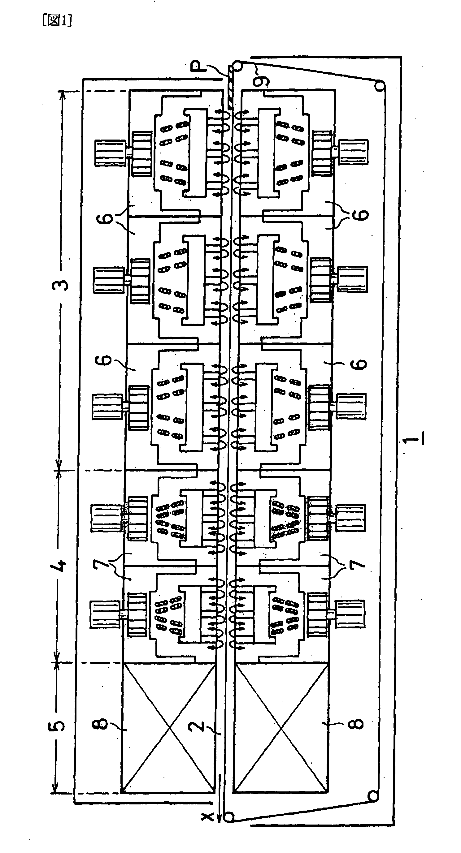
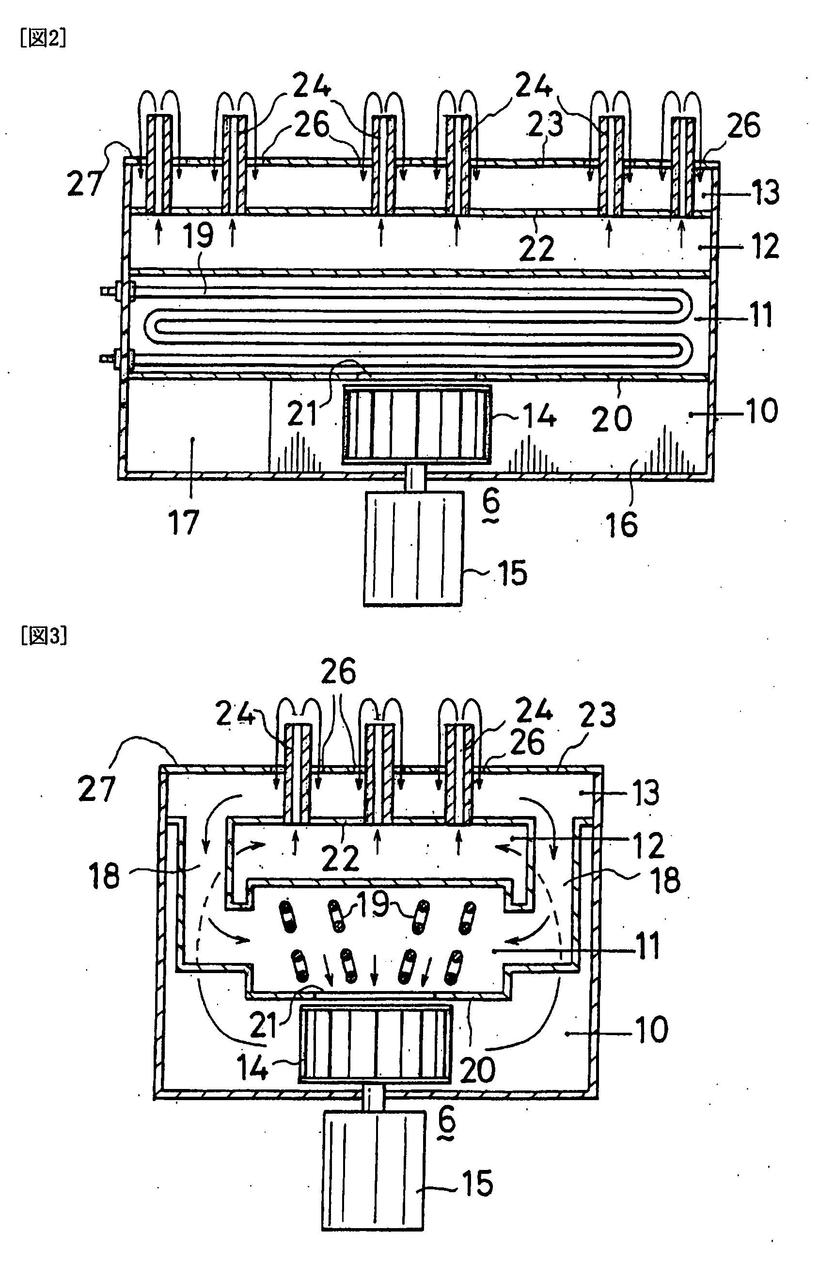
[0061]FIG. 1 is a front cross-sectional view of a reflow furnace according to the present invention, FIG. 2 is a front cross-sectional view of a hot air blowing heater installed in a reflow furnace according to the present invention, FIG. 3 is side cross-sectional view thereof, FIG. 4 is a partial perspective view of a hot air blowing heater installed in a reflow furnace according to the present invention, FIG. 5 is a plan view of FIG. 4, FIG. 6 is a cross-sectional view taken along line A-A of FIG. 5, FIG. 7 is a partial perspective view of a hot air blowing heater having a different structure installed in a reflow furnace according to the present invention, FIG. 8 is a plan view of FIG. 7, FIG. 9 is a cross-sectional view taken along line B-B of FIG. 8, FIG. 10 is a partial enlarged plan view of a mode in which the hot air discharge nozzles of FIG. 5 are formed from rectangular...
PUM
| Property | Measurement | Unit |
|---|---|---|
| Temperature | aaaaa | aaaaa |
| Shape | aaaaa | aaaaa |
Abstract
Description
Claims
Application Information