

Card Holder-Reader for Wallet Sized Cards
- Summary
- Abstract
- Description
- Claims
- Application Information
AI Technical Summary
Benefits of technology
Problems solved by technology
Method used
Image

Examples
first preferred embodiment
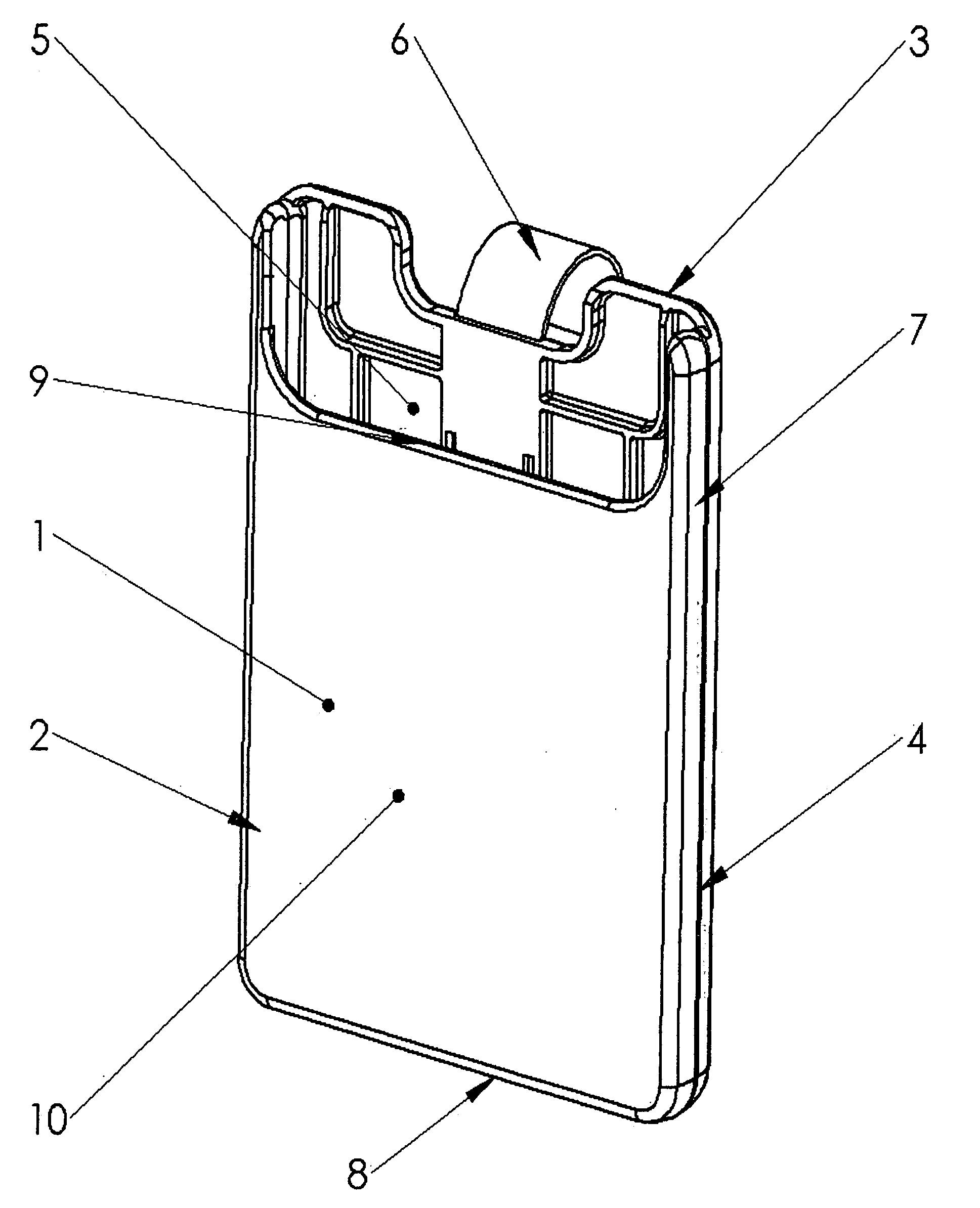
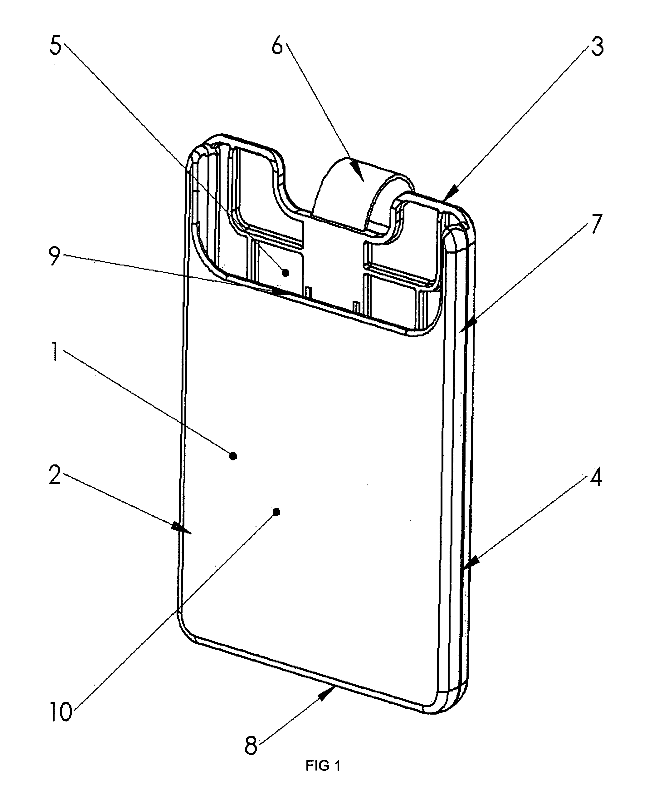
[0029]Referring to the drawings, wherein like parts are designated throughout with like numerals and symbols, FIG. 1 illustrates a front perspective view of the first preferred embodiment of the invention. In general, the body of the case 1 includes a front piece 2 and a back piece 3, joined together at seam 4, an opening 5 and a clip 6 attached to the back piece 3.
[0030]More specifically, the front piece 2 includes a front face 10, two side faces 7 and a lower face 8. A cutaway opening 9 in the front piece allows easier access to a card for insertion and removal. The front and back pieces are joined along the side faces 7 and lower face 8.
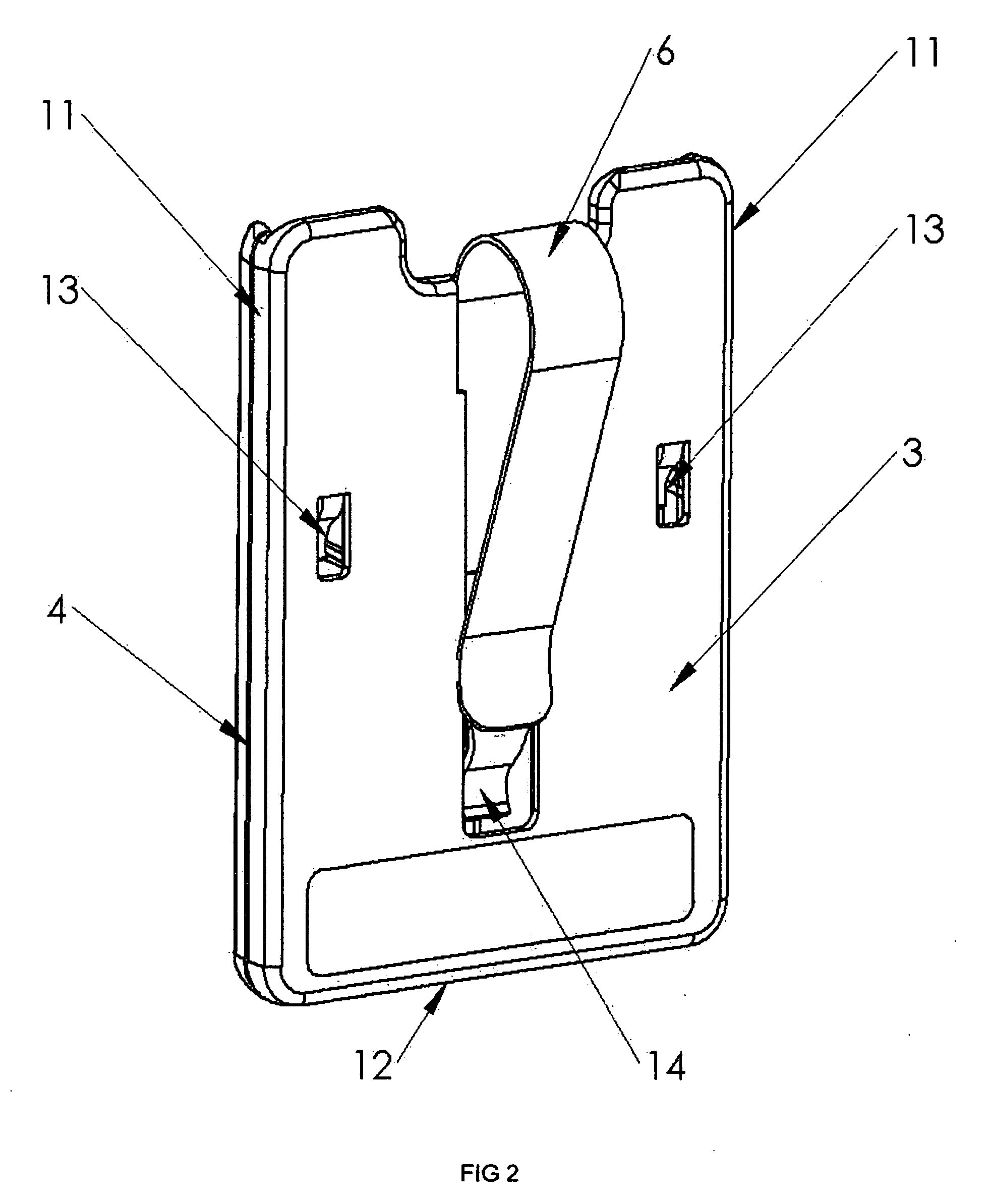
[0031]FIG. 2 illustrates a back perspective view of the case 1 with back piece 3 and clip 6 shown. The back piece also includes two side faces 11 and a lower face 12, along which the front and back pieces are joined by a seam 4. Preferably, the back piece 3 includes three integral tabs 13,14 which are part of the back piece 3. However, this design...
second preferred embodiment
[0035]Referring to the drawings, wherein like parts are designated throughout with like numerals and symbols, FIG. 6 illustrates a front perspective view of the second preferred embodiment of the invention. In general, the body of the case 1 includes a front piece 2 with a visual display 28, human interface 29, speaker 34, microphone 35, solar cell 33 and a back piece 3, joined together at seam 4, an opening 5 and a clip 6 attached to the back piece 3. The second embodiment contains all the details described in the first embodiment of the holder with the addition of the electronics and associated items, which are described in this section.
[0036]FIG. 7 illustrates schematically the body of the case in an exploded view with the front piece 2 on the left, back piece 3, clip 6, circuit board 30, card reader 31, visual display 28 and human interface 29. The circuit board 30 is shown mounted in the front piece 2, but may also be mounted in the back piece 3, providing other requirements ar...
PUM
 Abstract
Description
Claims
Application Information