Cylinder rings

Active Publication Date: 2009-05-28
LEICA GEOSYSTEMS AG
View PDF20 Cites 10 Cited by
  • Summary
  • Abstract
  • Description
  • Claims
  • Application Information

AI Technical Summary

Benefits of technology

[0009]An object on which the invention is based was, therefore, to provide a connection for the reception of acce

Problems solved by technology

The desired orientation of the rotary position cannot be achieved by means of simple threads on account of the relatively high tolerances in the engagement of the threads one into the other.
Such bayonets consist of h

Method used


Image

  • Cylinder rings
  • Cylinder rings
  • Cylinder rings

Examples


Example

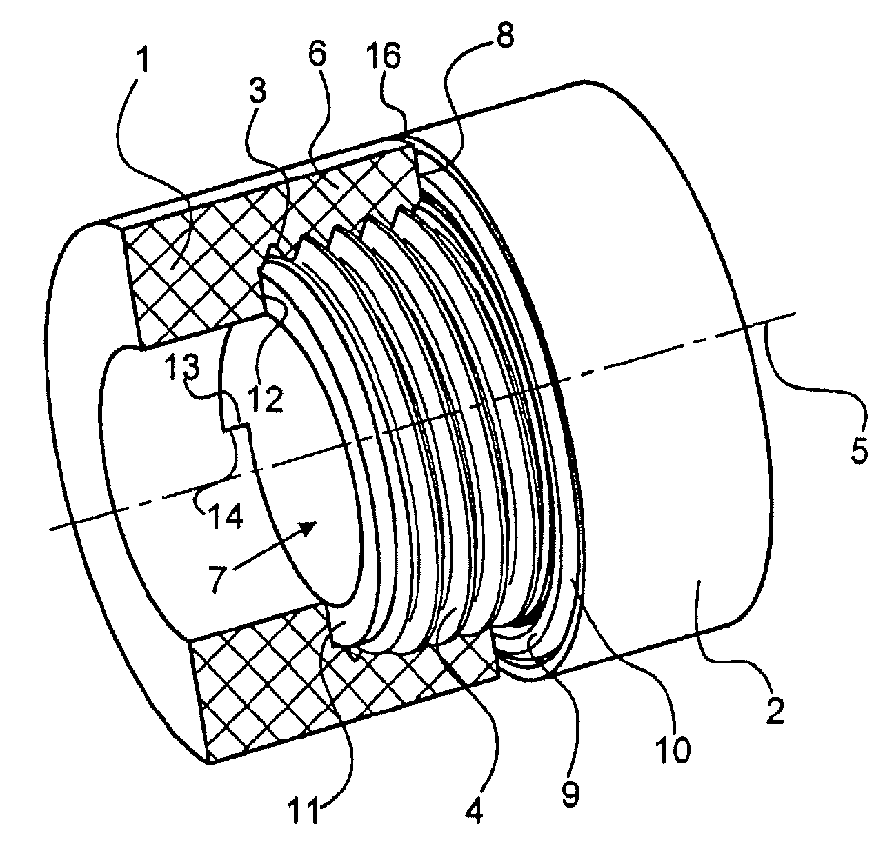
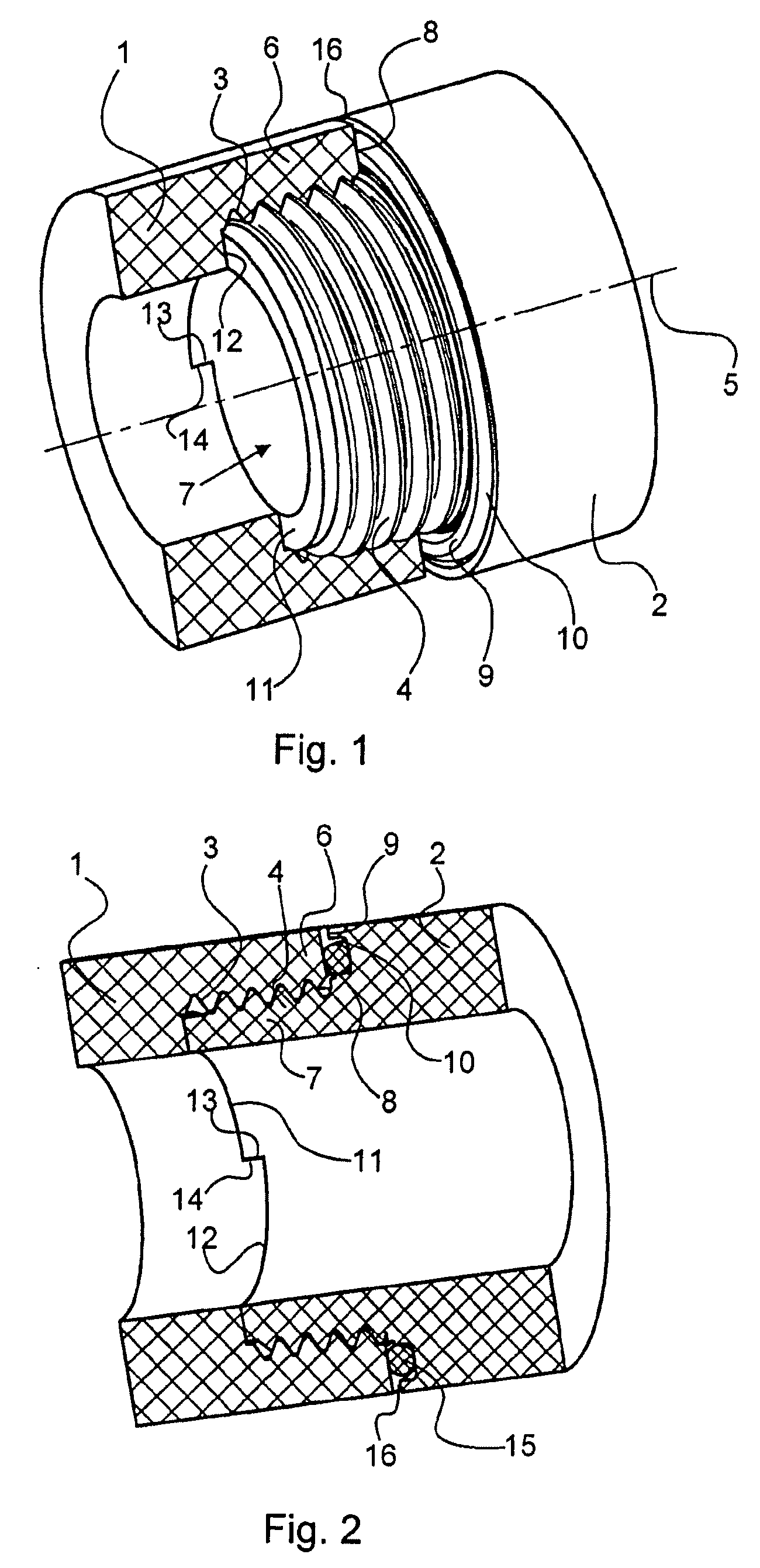
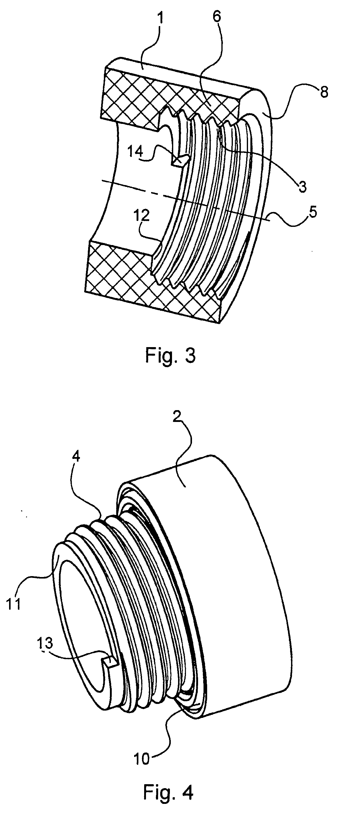
[0024]The system illustrated in FIG. 1 consists of two cylinder rings 1, 2 of identical wall thickness. A nut thread 3 is cut into the cylinder ring 1. The cylinder ring 2 is provided with a bolt thread 4. The threads running symmetrically with respect to the cylinder axis 5 are selected in their diameter such that sufficiently large wall thicknesses are obtained for the thread casing 6 of the nut thread 3 and for the thread core 7 of the bolt thread 4. The end face 8 of the thread casing 6 matches with a foot face 9 of the bolt thread 4. A slot 10 is introduced into the foot face 9 of the bolt thread 4.

[0025]The thread core 7 is designed on the end face as a first stop face 11. Correspondingly to this, a second stop face 12 is formed on the foot side of the nut thread 3. The stop faces 11, 12 axially limit the screwing movement in the axial direction and rise upward over a thread flight. The thread core 7 has no thread burr in this region, and therefore it constitutes an axially ri...


PUM


Abstract

Cylinder rings having single-start nut and bolt threads matched to one another and axial stop surfaces, running perpendicularly to the cylinder axis, between the cylinder rings are distinguished by the fact that the stop surfaces (11, 12) assigned to the nut thread (3) and the bolt thread (4) extend in an axially rising manner over at most one thread turn and each have at the end a step surface (13, 14) between the axially offset stop planes of the stop surfaces (13, 14).

Description

CROSS-REFERENCE TO RELATED PATENT APPLICATIONS[0001]This application is a Continuation-In-Part of U.S. Application PCT / DE2007 / 001301, filed Jul. 20, 2007, which is incorporated herein by reference in its entirety. The right of foreign priority is also claimed under 35 U.S.C. § 119(a) based on Federal Republic of Germany Application No. 10 2006 036 890.8, filed Aug. 4, 2006, the entire contents of which, including the specification, drawings, claims and abstract, are incorporated herein by reference.BACKGROUND OF THE INVENTION[0002]The invention relates to cylinder rings with mutually coordinated single-flight nut threads and bolt threads and with axial stop faces, running perpendicularly with respect to the cylinder axis, between the cylinder rings.[0003]Cylinder rings of this type are used in precision mechanical and optical apparatus construction for the screw connection of components or accessories. A nut thread on the front side of photographic objectives serves, for example, fo...

Claims


Application Information

Patent Timeline
IPC IPC(8): F16B39/10
CPCF16B33/002G03B17/14G02B7/022F16B33/02
Inventor SEITER, KAI OLIVER
Owner LEICA GEOSYSTEMS AG
Why Eureka
Try Eureka