High-sensitivity pressure-sensing probe

a pressure sensing probe and high-sensitivity technology, applied in the field of invasive medical devices, can solve problems such as heart tissue damage and even perforation of the heart wall, and achieve the effect of reducing the risk of heart disease and reducing the risk of strok

Active Publication Date: 2009-05-28
BIOSENSE WEBSTER (ISRAEL) LTD
View PDF102 Cites 440 Cited by
  • Summary
  • Abstract
  • Description
  • Claims
  • Application Information

AI Technical Summary

Benefits of technology

[0006]The embodiments of the present invention that are described hereinbelow provide novel apparatus and methods for sensing displacement of a joint, by generating and sensing magnetic fields using magnetic transducers, such as coils, on opposite sides of the joint. A disclosed embodiment relates specifically to the use of this sort of sensing apparatus in an invasive medical probe, in which the apparatus provides an indication of pressure exerted on the tip of the probe. The principles of the present invention, however, are similarly useful in applications of other sorts that require accurate sensing of joint displacement.

Problems solved by technology

Excessive pressure, however, may cause undesired damage to the heart tissue and even perforation of the heart wall.

Method used


Image

  • High-sensitivity pressure-sensing probe
  • High-sensitivity pressure-sensing probe
  • High-sensitivity pressure-sensing probe

Examples


Embodiment Construction

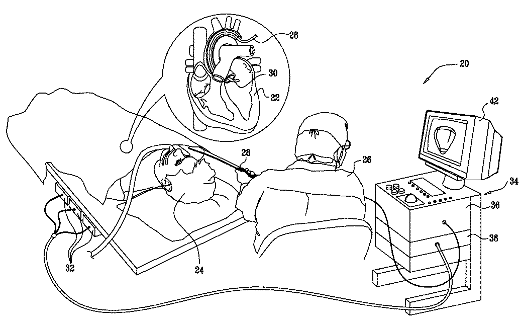
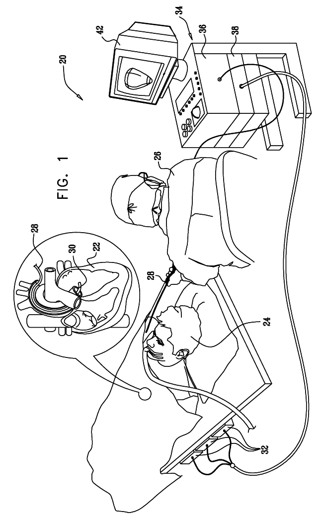
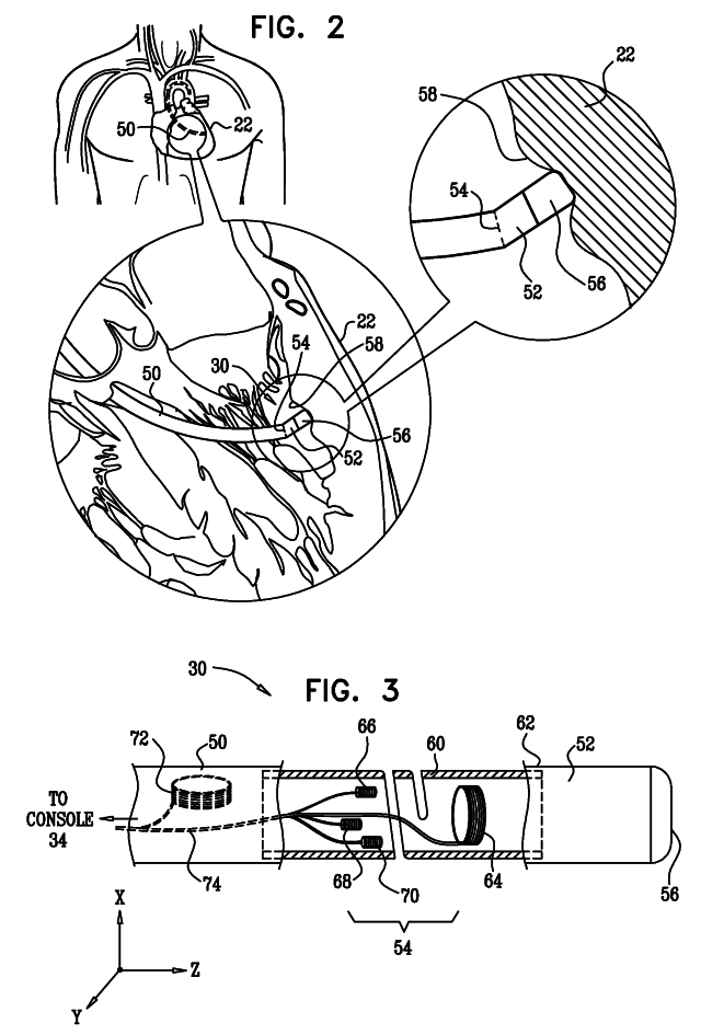
[0021]The above-mentioned U.S. patent application Ser. No. 11 / 868,733 describes a catheter whose distal tip is coupled to the distal end of the catheter insertion tube by a spring-loaded joint, which deforms in response to pressure exerted on the distal tip when it engages tissue. A magnetic position sensing assembly within the probe, comprising coils on opposite sides of the joint, senses the position of the distal tip relative to the distal end of the insertion tube. Changes in this relative position are indicative of deformation of the spring and thus give an indication of the pressure.

[0022]Embodiments of the present invention that are described hereinbelow provide a new design of the sensing assembly, which facilitates more precise measurement of tip movement. The configuration of the coils in this new design permits precise sensing of very small deflections and compressions of the joint connecting the catheter tip to the insertion tube. Therefore, the pressure on the tip can b...


PUM


Abstract

A medical probe includes an insertion tube, having a longitudinal axis and having a distal end. A distal tip is disposed at the distal end of the insertion tube and is configured to be brought into contact with a body tissue. A joint couples the distal tip to the distal end of the insertion tube. A joint sensor, contained within the probe, senses a position of the distal tip relative to the distal end of the insertion tube. The joint sensor includes first and second subassemblies, which are disposed within the probe on opposite, respective sides of the joint and each include one or more magnetic transducers.

Description

CROSS-REFERENCE TO RELATED APPLICATION[0001]This application is a continuation-in-part of U.S. patent application Ser. No. 11 / 868,733, filed Oct. 8, 2007, which is assigned to the assignee of the present patent application and whose disclosure is incorporated herein by reference.FIELD OF THE INVENTION[0002]The present invention relates generally to invasive medical devices, and specifically to methods and devices for sensing displacement of a joint in a probe, such as a catheter, that is applied to the body of a patient.BACKGROUND OF THE INVENTION[0003]In some diagnostic and therapeutic techniques, a catheter is inserted into a chamber of the heart and brought into contact with the inner heart wall. In such procedures, it is generally important that the distal tip of the catheter engages the endocardium with sufficient pressure to ensure good contact. Excessive pressure, however, may cause undesired damage to the heart tissue and even perforation of the heart wall.[0004]For example,...

Claims


Application Information

Patent Timeline
Patent Type & Authority Applications(United States)
IPC IPC(8): A61B18/18
CPCA61B1/0008A61B5/06A61B5/065A61B5/6885A61B18/1492A61B2018/00351A61B5/48A61B2019/465A61B2019/5251A61B2019/5458A61B2562/0247A61N1/056A61N1/08A61B2019/464A61B2090/064A61B2090/065A61B2034/2051A61B2090/3958A61B1/00097
Inventor GOVARI, ASSAFEPHRATH, YARONGARCIA, ARIELALTMANN, ANDRES CLAUDIO
Owner BIOSENSE WEBSTER (ISRAEL) LTD
Why Eureka
Try Eureka