Amplifier System

a technology of amplifiers and amplifiers, applied in the field of amplifier systems, can solve the problems of limited types of operation data that can be displayed on the amp page and group page, and the inability to monitor the operation data of the entire group collectively, and the inability to monitor the operation data of the entire group

Active Publication Date: 2009-05-28
YAMAHA CORP
View PDF7 Cites 26 Cited by
  • Summary
  • Abstract
  • Description
  • Claims
  • Application Information

AI Technical Summary

Benefits of technology

[0011]In view of the foregoing, it is an object of the present invention to provide an amplifier system in which a plurality of amplifiers and an amplifier control apparatus are connected via a network, and which has a function for not only allowing detailed o

Problems solved by technology

With the conventionally-known amplifier control apparatus, the operation data of the amplifiers can be displayed and monitored on the pages of the main window, but types of the operation data that can be displayed on the Amp page and Group page are limited.
However, the conventional amplifier control apparatus present the problem that detailed operation data of the amplifiers can be monitored only channel by channel.
Besides, the operation data are displayed on the Group View page per channel of the channel in question, so that the operation data of the entire group can not be monitored collectively.
Furthermore, the user may sometimes want to monitor the maximum value of some of level data, such as input and output levels, of the operation data, and the user may sometimes want to monitor the minimum value of other level data; however, so far, it has been impossible to monitor the maximum and minimum data values as desired.
Further, in such a case, it is conceivable to synthesize level data of the individual amplifiers of the group and display s

Method used


Image

  • Amplifier System
  • Amplifier System
  • Amplifier System

Examples


Embodiment Construction

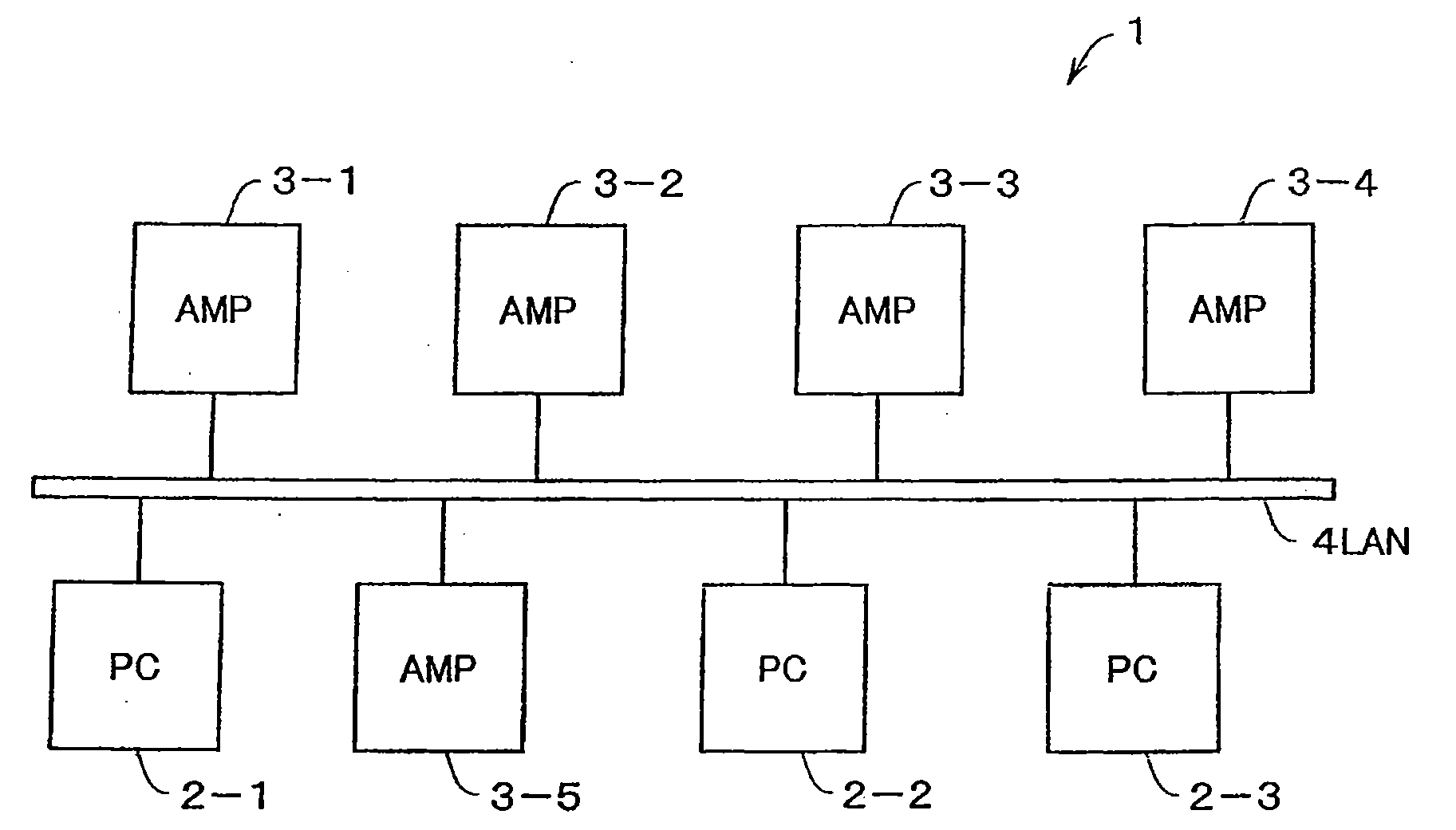
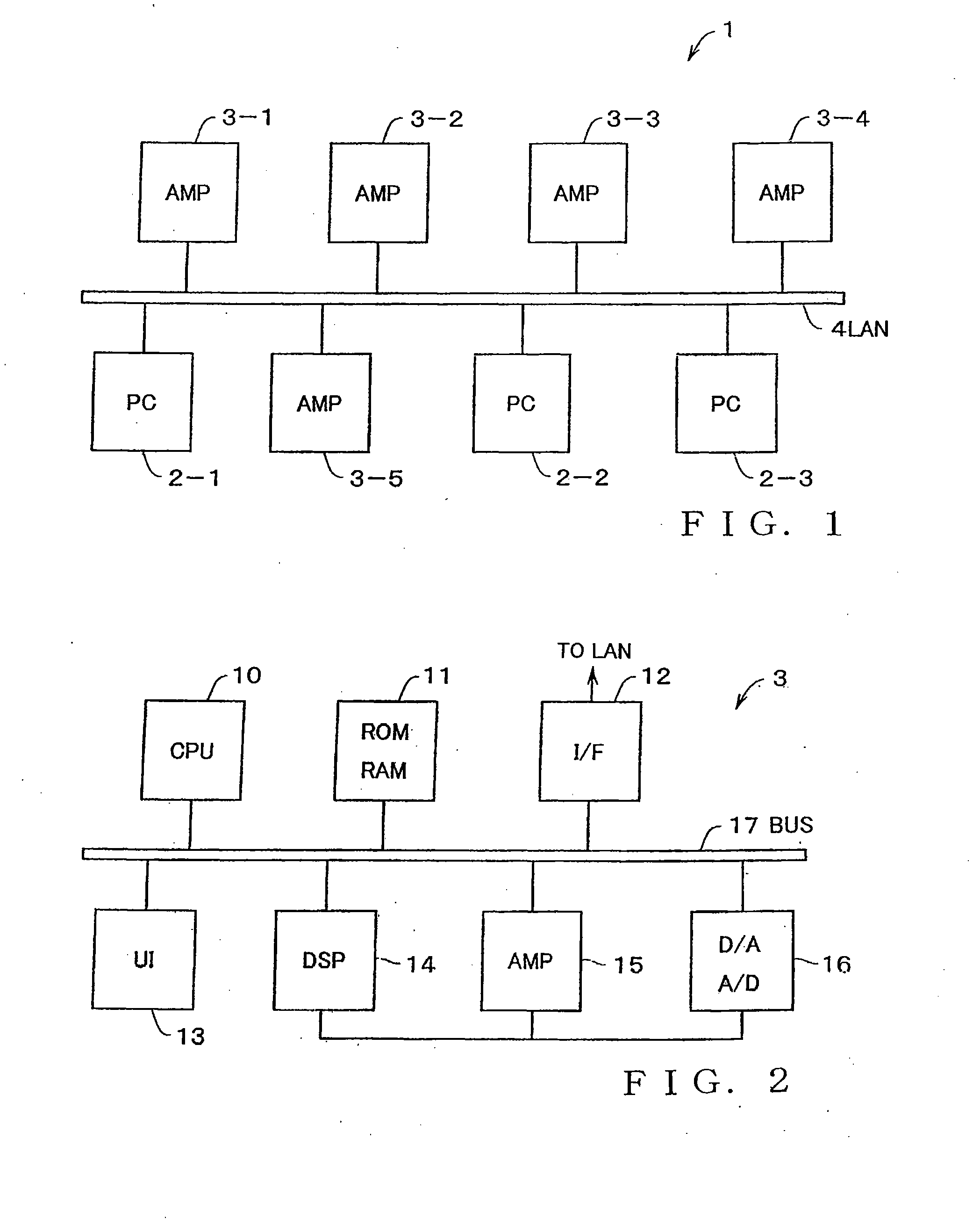
[0075]FIG. 1 is a block diagram showing a general setup of an amplifier system according to an embodiment of the present invention. The amplifier system 1 shown in FIG. 1 includes a LAN (Local Area Network) 4 to which are connected, for example, three personal computers (hereinafter referred to as “PCs”) 2-1, 2-2 and 2-3 and five amplifiers 3-1, 3-2, 3-3, 3-4 and 3-5. Communication control of the LAN 4 is performed, for example, by the Ethernet standard that is a communication control standard commonly used today. Each of the three amplifiers has amplifier manager software installed therein. With the amplifier managers activated on respective operating systems ((hereinafter referred to as “OSs”) of the PCs 2-1-2-3, it is possible to monitor, via the LAN 4, operating states of the amplifiers 3-1-3-5 connected to the LAN 4 and remote-control the operation of the amplifiers 3-1-3-5 via the LAN 4. In this case, only one of the PCs which has acquired a right of control over an amplifier ...


PUM


Abstract

When any one of a plurality of amplifiers has been selected in response to amplifier selecting operation, an amplifier Detail View of the selected amplifier is displayed, where corresponding parameters are displayed via elements of the amplifier Detail View. When any one of a plurality of groups has been selected in response to group selecting operation, a group Detail View of the selected group is displayed, where maximum and minimum values detected from among values of a parameter of individual amplifiers of the selected group are displayed via a band-shaped element of a corresponding fader element. In another example, where a hierarchical group is selected in a tree display section on a control screen, respective state information, including parameter values or states of parameters, of a plurality of amplifiers belonging to the selected hierarchical group is displayed in a state information section.

Description

BACKGROUND[0001]The present invention relates to an amplifier system where a plurality of amplifiers connected to a network is controlled by an amplifier control apparatus.[0002]Heretofore, there have been known professional-use audio systems which are employed in sound amplification apparatus (PA (Public Address System)) in concert halls, theaters, etc. in music production, etc. Such audio systems use many audio amplifiers that amplify sound signals and supply the amplified sound signals to many speakers provided at predetermined positions. In this connection, amplifier systems which are applied to networked audio systems and in which a plurality of amplifiers and amplifier control apparatus are connected to a network so that the plurality of amplifiers are controlled by the amplifier control apparatus.[0003]In each of such amplifier systems, amplifier manager software is pre-installed in a personal computer, and the personal computer and the plurality of amplifiers are connected v...

Claims


Application Information

Patent Timeline
IPC IPC(8): G05B19/418G06F3/048
CPCH04R27/00H04R2227/003H04R29/008H04R29/007
Inventor KOHYAMA, NAOHIDEIWAYAMA, KENSUYAMA, AKIOMUTO, TAKAAKIMAKINO, TAKAAKI
Owner YAMAHA CORP
Why Eureka
Try Eureka