
Isokinetic sampling method and system for multiphase flow from subterranean wells

a multi-phase flow, isokinetic technology, applied in the direction of volume/mass flow measurement, measurement devices, instruments, etc., can solve the problems of liquid carry-over in the separator gas outlet line, poor measurement of gor and non-representative pvt samples, and inability to cope with high flow rate. , to achieve the effect of improving the determination of relevant flow parameters

Inactive Publication Date: 2009-06-04
SCHLUMBERGER TECH CORP
View PDF20 Cites 44 Cited by
  • Summary
  • Abstract
  • Description
  • Claims
  • Application Information

AI Technical Summary

Benefits of technology

[0013]In yet another embodiment, existing and well-known multiphase flow measurements, such as a nuclear densitometer and/or a venturi meter may be

Problems solved by technology

Furthermore, PVT data may often have a significant impact on processing facility designs and specifications, and therefore on the profitability of gas-oil field.
Common analysis sampling procedures suffer from deficiencies in either or both of their accuracy and their ability to cope with high flow rates.
For example, a high-rate gas condensate well producing 5-100 MMscf (Millions standard cubic feet) / day with a gas-oil ratio of 3 k-100 k scf / bbl (CGR from 0 to 200 bbl / MMscf) (bbl=barrel of liquid; 1 m3=6.29 bbl), can often overwhelm a test-separator, causing liquid carry-over in the separator gas outlet line, thereby providing poor measurement of the GOR and non-representative PVT samples (if the carry-over is not measured and corrected for).
This normally also results in poor recombination ratios.
Gas condensate wells are particularly problematic for sampling because large volumes of gas are associated with only small volumes of liquid and, as such, the phase behavior will be highly sensitive to the quantity and composition of the liquid phase.

Method used


Image

  • Isokinetic sampling method and system for multiphase flow from subterranean wells
  • Isokinetic sampling method and system for multiphase flow from subterranean wells
  • Isokinetic sampling method and system for multiphase flow from subterranean wells

Examples


Embodiment Construction

[0023]The ensuing description provides preferred exemplary embodiment(s) only, and is not intended to limit the scope, applicability or configuration of the invention. Rather, the ensuing description of the preferred exemplary embodiment(s) will provide those skilled in the art with an enabling description for implementing a preferred exemplary embodiment of the invention. It is being understood that various changes may be made in the function and arrangement of elements without departing from the spirit and scope of the invention as set forth in the appended claims. Specific details are given in the following description to provide a thorough understanding of the embodiments. However, it will be understood by one of ordinary skill in the art that the embodiments maybe practiced without these specific details. For example, circuits may be shown in block diagrams in order not to obscure the embodiments in unnecessary detail. In other instances, well-known circuits, processes, algorit...


PUM


Abstract

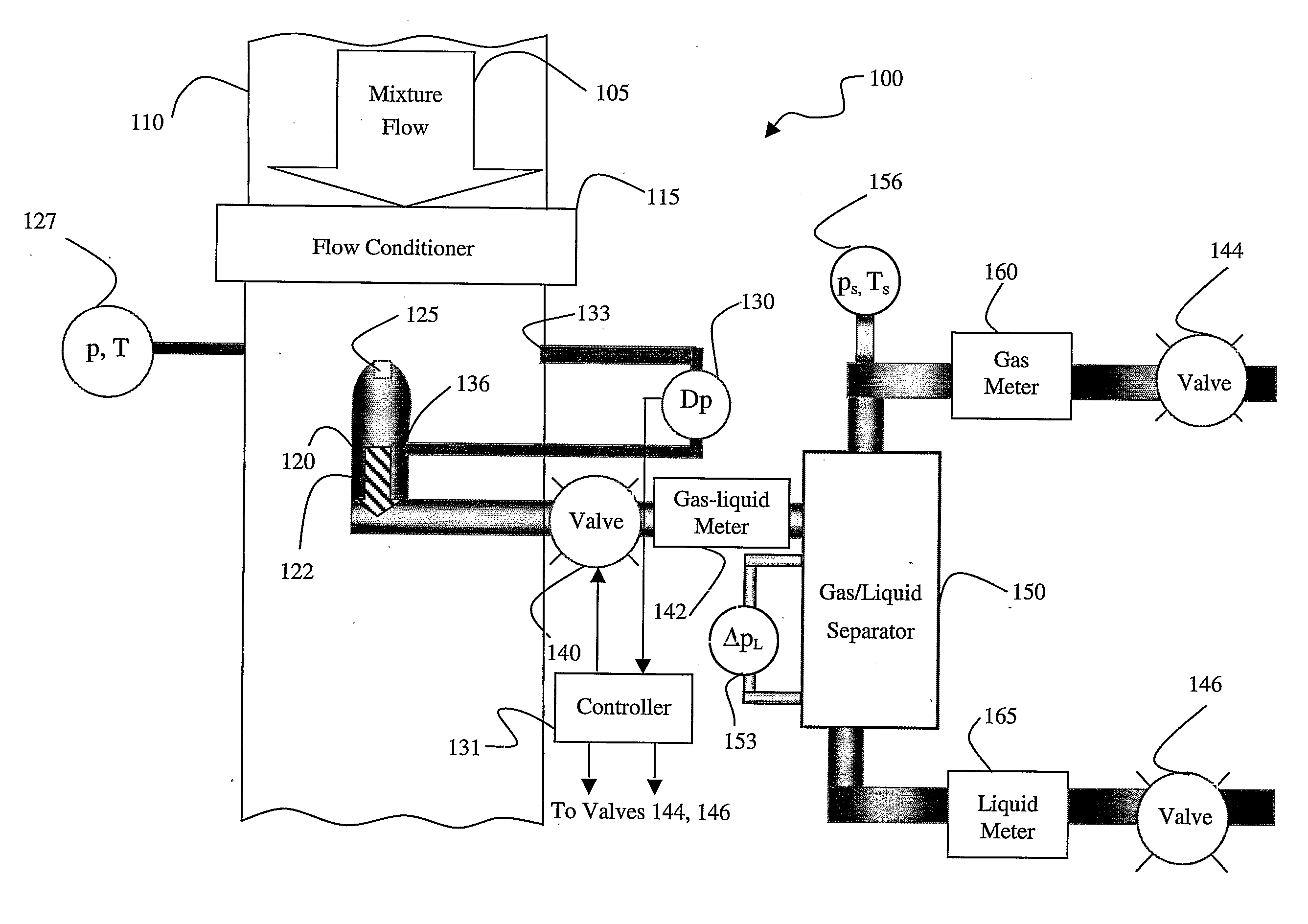
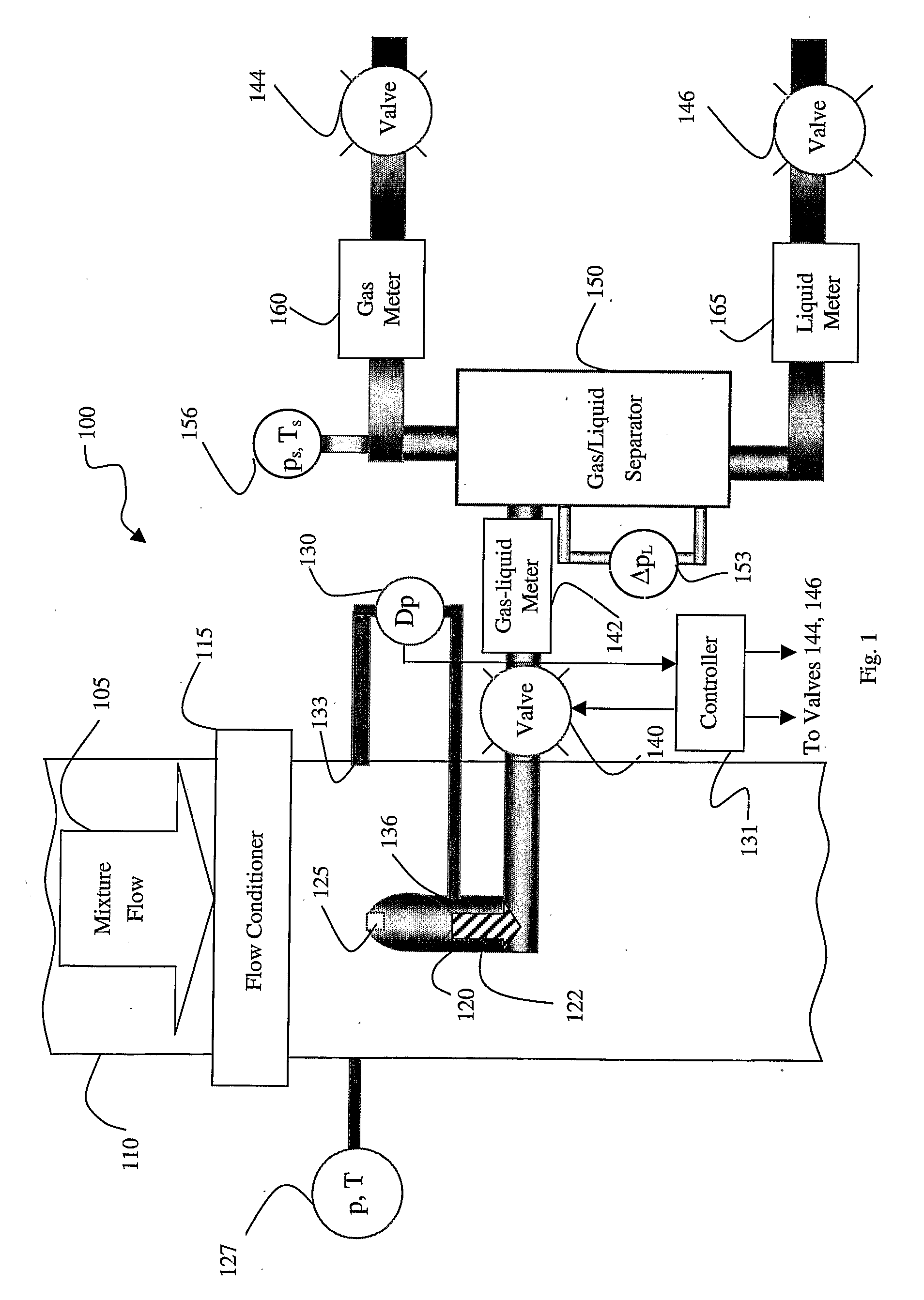
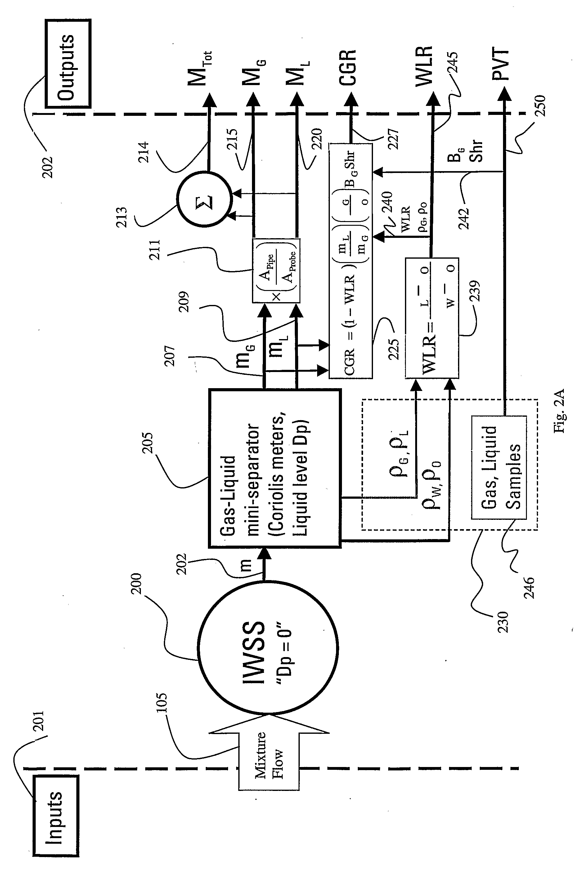
The invention relates in a one aspect to a method or apparatus for measuring flow properties of a multiphase fluid stream flowing in a pipeline comprising means for sampling, with a sampling probe, a portion of the fluid stream; for measuring a differential pressure between a first pressure of the fluid stream in the pipeline and a second pressure of the portion of the fluid stream in the sampling probe; for controlling flow rate of the sampled portion, wherein the flow rate of the sampled portion is controlled to provide for nullification of the differential pressure in order to obtain substantially isokinetic sampling of the fluid stream; for measuring properties of the portion of the fluid stream; and for processing the measured properties to determine the flow properties of the multiphase fluid stream flowing in the pipeline, wherein the above elements do not require- or are performed without the determination of the density of fluid in the fluid stream through nuclear radiation methods.

Description

[0001]This disclosure relates in general to methods and systems for measuring flow properties of a multiphase mixture flowing in a pipeline, where the pipeline is configured to transport hydrocarbons. More specifically, but not by way of limitation, certain embodiments of the present invention provide methods and systems in which samples of the multiphase mixture flowing in the pipeline, which mixture generally comprises hydrocarbons in liquid and gaseous phases and water, are collected from the pipeline under isokinetic conditions and properties of the samples are measured and processed to determine the flow properties of the multiphase mixture flowing in the pipeline. In one embodiment of the present invention, liquid and gas phases of the samples taken under isokinetic conditions from the flowing multiphase mixture may be separated from one another and passed through one or more Coriolis meters to determine, among other things, mass flow rates of the gas phase and / or the liquid p...

Claims


Application Information

Patent Timeline
IPC IPC(8): G01F1/74G01F15/02
CPCG01F15/02G01F1/74G01N1/2035G01N1/22
Inventor XIE, CHENG-GANG
Owner SCHLUMBERGER TECH CORP
Learn More