Eureka AIR delivers breakthrough ideas for toughest innovation challenges, trusted by R&D personnel around the world.

Conveyor system for the transport of passengers/goods

a conveyor system and passenger technology, applied in the direction of conveyors, escalators, transportation and packaging, etc., can solve the problems of inability to reduce the dimensions of the conveyor system, the contact between the chain link of the linear actuation system and the chain link connected to the steps or pallets is not easy, and the conveyor system is not easy to operate. the effect of reducing the height of the upper and lower end sections, improving the comfort and safety of passengers

Inactive Publication Date: 2009-06-04
THYSSENKRUPP ELEVATOR ES PBB
View PDF4 Cites 22 Cited by
  • Summary
  • Abstract
  • Description
  • Claims
  • Application Information

AI Technical Summary

Benefits of technology

[0005]A conveyor system, such as a moving walkway designed according to this invention, which can operate in both directions of transport improves the comfort and safety of the passenger, reduces the height of the upper and lower end sections of the conveyor system, reduces the cost of the conveyor system, eliminates the need for extensive civil construction job to create a pit and enable a portable moving walkway system.
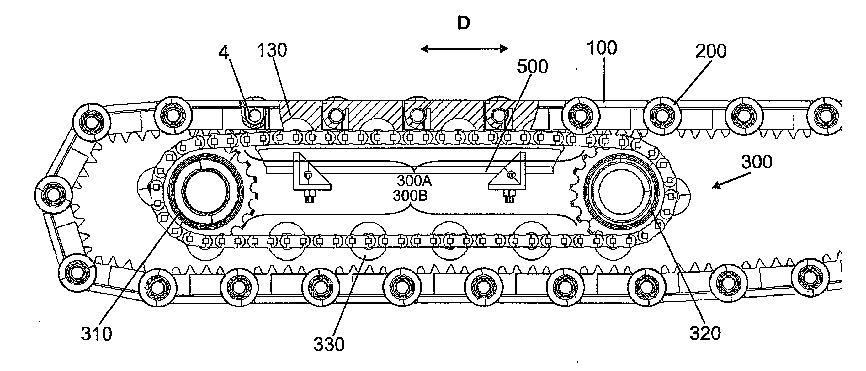
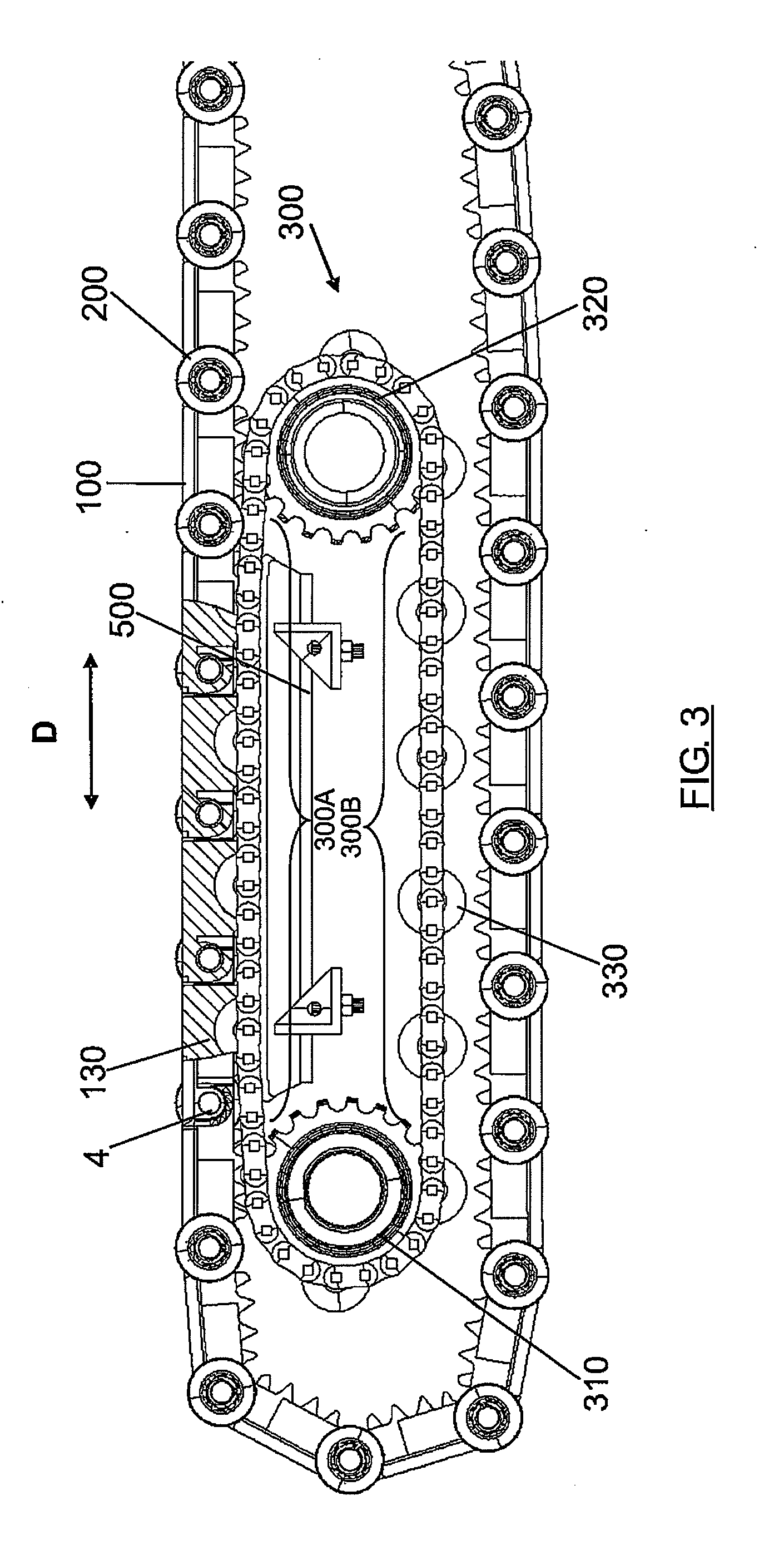
[0006]The pallet actuation system for the proposed moving walkway includes a small horizontally arranged geared motor, short pallets specially designed with upper grooves, small actuation gear wheels, actuation shafts and a drive chain formed by transmission chains and a plurality of separate deformable rollers. The drive chain directly meshes with a claw or first arc-shaped engagement means designed under each of the traction links. The short pallet allows the radius of the return section to be small and therefore the upper and lower heads of the conveyor system can be designed with a smaller height in comparison with solutions in the state of the art. The small teeth and the claw are designed under each traction link. The pallets can be part of the traction chain and its linkage is located close to the bearing surface, allowing a small transition radius for inclined walkways. The deformable drive roller meshes with the claw under the traction link. When the drive rollers experience deformation above a certain level due to a high contact force, the lower teeth can mesh with the drive chain. Such design assures that the high force is shared between the deformable drive rollers and the drive chain. Furthermore if the shaft-pin or rod of the drive rollers breaks for any reason, the actuation system will continue to operate safely.
[0033]when the drive roller is deformed in the first engagement to prevent large loads on said roller.
[0049]These first, second and third outer layers allow the gears between the different elements involved in transmitting movement to be much smoother than with metal-metal contact, which involves quieter operation and with dampened contacts between starting and end engagement moments in addition to elongating the useful life of said elements.
[0052]In addition, the drive chains can have, coaxially to each of its linkages, a guide roller completely defining, by means of a guide and a counter-guide, the path to be followed by the chain, allowing the chain to work by being pushed and preventing the necessary tension in the tension shaft of said chain so that it can work by being pulled.
[0053]In summary, the invention relates to a pallet actuation system moving the pallets of a moving walkway through drive chains directly engaging the lower part of the traction chains. The drive chain has separate drive rollers which are made of deformable and elastic materials. The links of the traction chain are designed with teeth and claws in the lower part to mesh with the drive chain and the rollers. The short pallet and the traction system allow a small radius in the return section and, therefore, reduce the height of the heads of the walkway. Furthermore, since the connecting shaft is located close to the surface of the pallet, it is possible to design inclined moving walkways with smaller transition radiuses without opening large gaps between the pallets, reducing the total length of the moving walkway for a specific elevation and allowing the gaps existing between pallets to be decreased. This system allows more than one actuation to be located in different parts of the walkway. The total dimensions of the moving walkway are reduced with this invention and low noise and vibration levels are assured, improving user comfort.

Problems solved by technology

Given that the gap between two consecutive pallets is limited to meet safety requirements, the transition radius in inclined walkways is limited.
Nevertheless, the metal to metal contact between the chain of the linear actuation system and the chain links connected to the steps or pallets makes noise.
The general configuration proposed in these documents does not allow the possibility of reducing the dimensions of the conveyor.

Method used


Image

  • Conveyor system for the transport of passengers/goods
  • Conveyor system for the transport of passengers/goods
  • Conveyor system for the transport of passengers/goods

Examples


Embodiment Construction

[0064]The invention will be described as being applied to a moving walkway. However, it must be understood that the concepts described in this specification can also be applied to other types of conveyor systems. It must also be indicated that the system of the invention can operate in both directions of transport of a load / people.

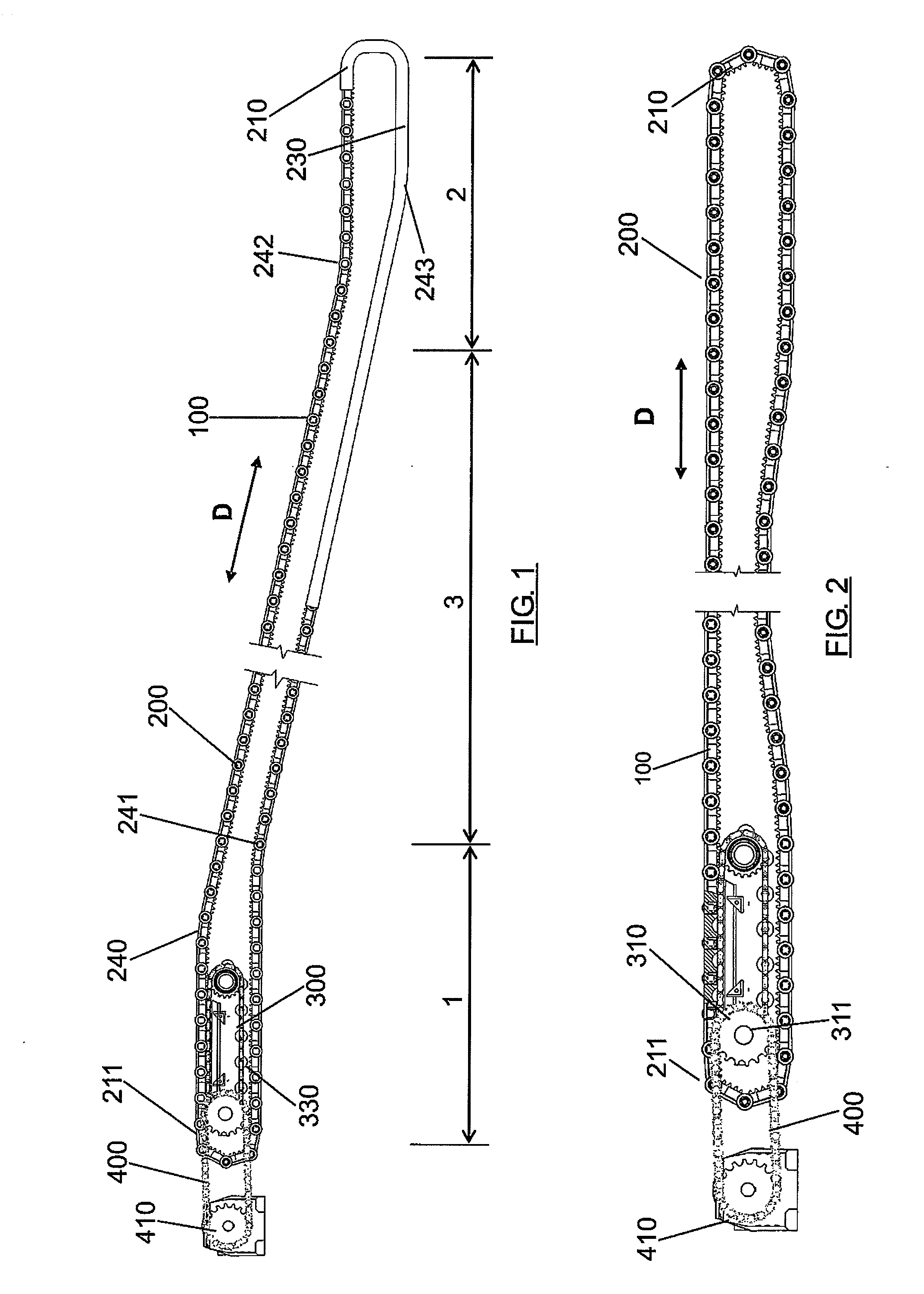
[0065]FIG. 1 shows a moving walkway having a supporting structure comprising an upper end section or head (1), a lower end section or head (2) and an intermediate section (3). A worm belt is made up of a series of links (100) which are connected by shafts-pins (4). These links (100) are held by bearing rollers (200) which are led by means of guides (230) designed in the bearing profile of the moving walkway. The guides (230) comprise an upper return section (211) and a lower return section (210) leading the links (100) at both ends of the system. The radiuses of the upper return section (211) and of the lower return section (210) can be small, greatly redu...


PUM


Abstract

The invention relates to a pallet actuation system moving the pallets of a moving walkway through drive chains directly engaging the lower part of the chains of traction links. The drive chain has separate drive rollers which are made of deformable and elastic materials. The links of the traction chains are connected together by connecting shafts and have teeth and claws in the lower part to mesh with the drive chain and the rollers.

Description

FIELD OF THE INVENTION[0001]The invention relates to a passenger or goods conveyor system and, more particularly to a moving walkway pallet actuation system.BACKGROUND OF THE INVENTION[0002]Conventional passenger conveyor devices such as mechanical stairs or moving walkways include a chain of steps or pallets which shift in a loop to provide continuous movement along a specific trajectory. The steps or pallets are connected to said chain link loop of steps or pallets acting together with an actuation system. The actuation system normally consists of a chain of steps or pallets, actuation gear wheels, a shaft and an electric drive motor. The drive motor actuates the drive gear wheel which conveys movement to the links of the chain of steps or pallets. While the links of this chain move, the steps or the pallets move as desired.[0003]To assure small speed fluctuation and to minimize the polygon effect in the conventional conveyor system, a large number of teeth are required on the act...

Claims


Application Information

Patent Timeline
Patent Type & Authority Applications(United States)
IPC IPC(8): B65G23/02
CPCB66B23/028B65G23/16
Inventor GONZALEZ ALEMANY, MIGUEL ANGELGONZALEZ PANTIGA, JUAN DOMINGOOJEDA ARENAS, JOSE
Owner THYSSENKRUPP ELEVATOR ES PBB
Why Eureka
Eureka Blog
Learn More