Expansion Injection Molding Process And Mold For Expansion Injection Molding

a technology of expansion injection molding and expansion injection molding, which is applied in the field of expansion injection molding process and mold for expansion injection molding, can solve the problems of not being able to be used as practical products that require good appearance, the external surface of expansion molded articles will have a great amount of appearance defect, swirl marks, etc., and achieves short molding cycle, prevent swirl marks on the surface of molded articles, and good appearance

Inactive Publication Date: 2009-06-04
PRIME POLYMER CO LTD
View PDF2 Cites 21 Cited by
  • Summary
  • Abstract
  • Description
  • Claims
  • Application Information

AI Technical Summary

Benefits of technology

[0050]According to the present invention, the occurrence of swirl marks on the surface of a molded article is prevented and it is possible to obtain expansion injection-molded articles having good appearance in a short molding cycle at a low cost.
[0051]Moreover, according to the present invention, air leakage does not occur because a sealing member arranged on one facing surface come into firm contact with the other facing surface or a sealing member arranged thereon at its entire circumference when the gas pressure in the cavity is increased. Furthermore, wear of the sealing members for maintaining airtightness is suppressed.

Problems solved by technology

In the above-mentioned expansion injection molding process, however, the external surface of an expansion molded article will have a great amount of defect in appearance, called swirl mark, which appears when expanding gas dissolved in molten resin breaks and the part is drawn.
Therefore, such articles could not be used as practical products required having good appearance.
Even in this method, however, it is difficult to retain the pressure of resin charged when the injection speed decreases at a flow front or at a section where the shape of a molded article changes greatly; and it was impossible to completely suppress the occurrence of swirl marks in the external surface of a molded article.
Therefore, the cost of molds was high.
Moreover, in order to add such a high pressure to the inside of a mold, it takes time to increase the pressure of the gas in the cavity itself and therefore a cycle time itself is also long.
This is a major factor of high product costs.
However, the increase continues only for a moment and it was impossible to keep the pressure during injection.
Therefore, there are limits in speeding up of the molding process.
A large flow resistance is produced when gas passes through the parting portion when the gas is charged into and discharged from the cavity and, therefore, there are limits in speeding up of the charging and discharging of gas.
For this reason, the above-mentioned counter pressure method, which makes the molding cycle longer, is difficult to be adopted.

Method used


Image

  • Expansion Injection Molding Process And Mold For Expansion Injection Molding
  • Expansion Injection Molding Process And Mold For Expansion Injection Molding
  • Expansion Injection Molding Process And Mold For Expansion Injection Molding

Examples


example 1

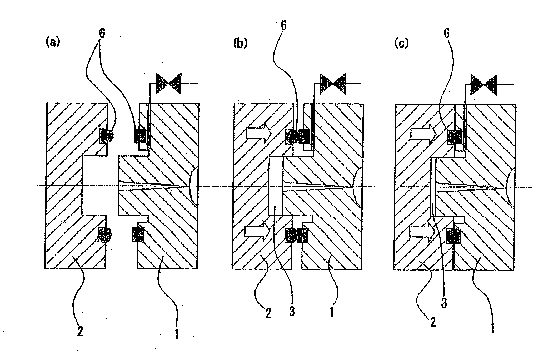
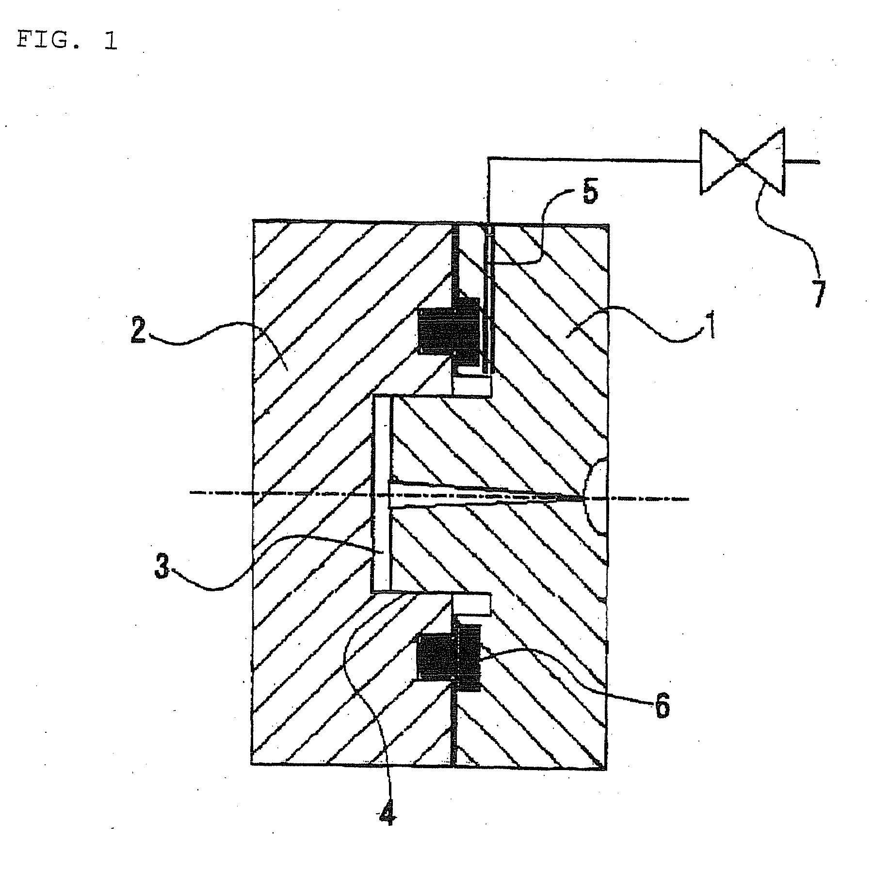
[0102]A mold shown in FIG. 1, which has a cavity size of 800×500 mm, was prepared. This mold has a structure such that the thickness of the cavity can be changed by the thickness of an insert of its gas-sealed part. Through fixation of an insert having a predetermined thickness to the movable mold across a rubber O-ring having a circular cross section, the mold was adjusted to have a cavity thickness of 1.5 mm when the mold is in a completely closed state.

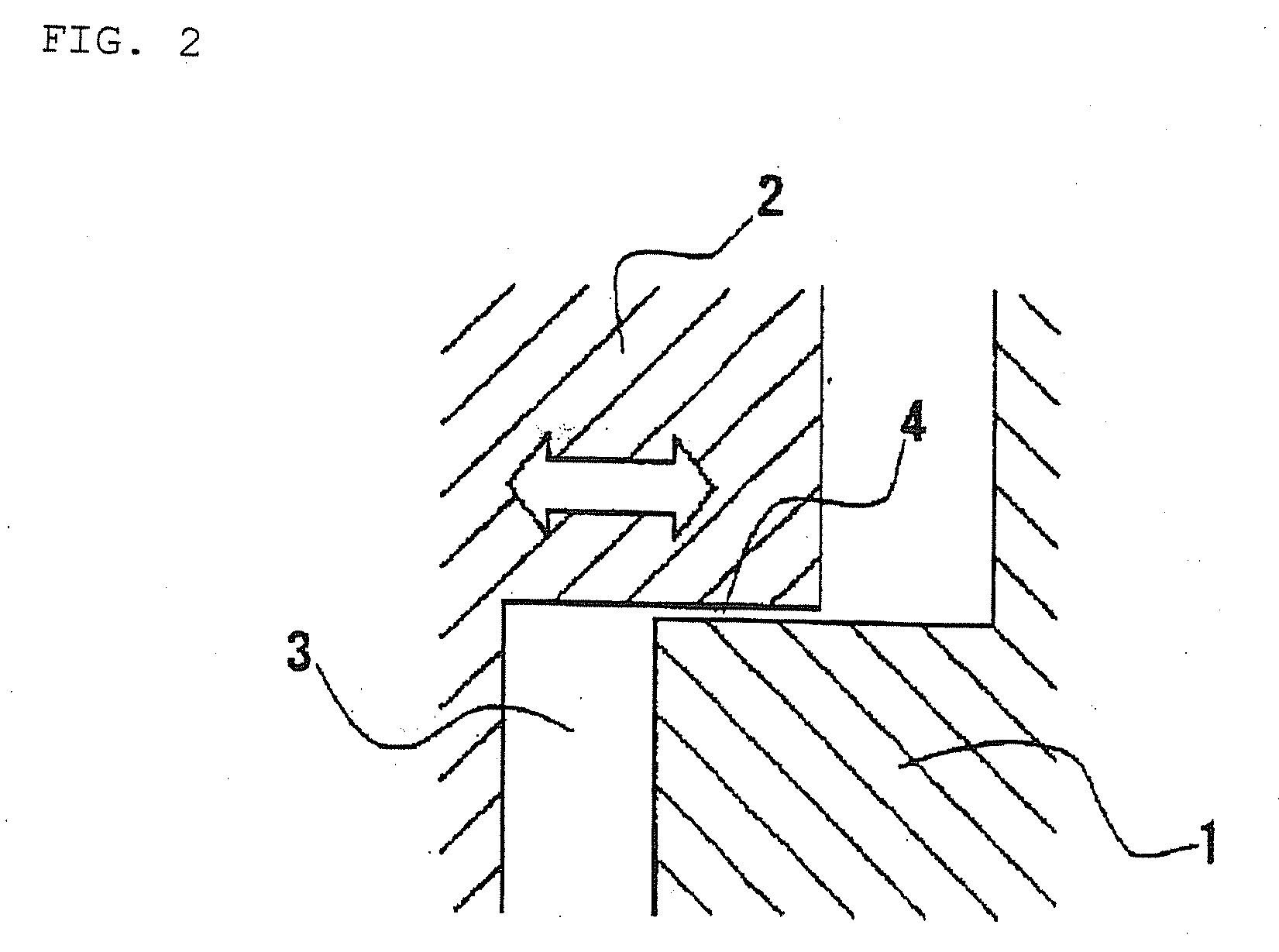
[0103]The surrounding of the cavity of this mold forms a shear edge structure. In the outer periphery of the base end of the convex part in the fixed mold, a looped gas passageway having a width of 5 mm and a height of 15 mm is provided, where the width is defined by the gap between the convex part and the insert and the height is defined by the thickness of the insert. This gas passageway is interconnected to the cavity through the gap of the shear edge.

[0104]The arrangement of an O-ring on the movable mold made it possible to est...

reference example 2

[0112]The supply pressure of the expansion agent and the gas pressure in the cavity were equal to those used in Example 1. The pressure in the cavity was maintained also after the completion of injection of a molten resin into the cavity. Release of the pressure was started during the step of enlarging the cavity volume by moving the movable mold. Some pockmarks and defective expansion were generated in the surface of the expansion molded article because the timing of starting the gas discharge was later than a preferable range. It, however, was confirmed that there were no swirl marks. The molding conditions and the results derived therefrom are shown in Table 1.

TABLE 1ComparativeReferenceReferenceExample 1example 1example 1example 2ResinPPPPPPPPExpansion agentCO2 GasCO2 GasCO2 GasCO2 GasExpansion agent1.51.51.51.5Pressure (MPa)Gas Pressure in0.30.00.90.2Cavity (MPa)Timing of GasCompletionCompletionCompletionDuringDischargingofofofExpansionInjectionInjectionInjectionStepResin Charg...

example 2

[0113]Injection molding was carried out in the same manner as Example 1 except that, as an expansion agent, sodium hydrogencarbonate and a citric acid-based thermal decomposition type chemical expansion agent were used. The chemical expansion agent was supplied in such a manner that it was added in the form of masterbatch in an amount of 3 parts to the material and then mixed.

[0114]Into a cavity where the pressure was increased to about 0.2 MPa by mold closure of the molding machine, a molten polypropylene resin was injected, the resin having been prepared by melting and dissolving carbon dioxide generated from a chemical expansion agent decomposed on heating. At the time when the injection was completed, the gas pressure in the cavity was released and the movable mold was moved so that the volume of the cavity would be enlarged in 0.5 seconds from the completion of the injection. Thus, an expansion molded article having no swirl marks in its surface was obtained. The evenness of th...


PUM

PropertyMeasurementUnit
gas pressureaaaaaaaaaa
cavity thicknessaaaaaaaaaa
thicknessaaaaaaaaaa

Abstract

To provide an expansion injection molding process, which is freed from the occurrence of swirl marks on the surface of a molded article and by which foamed injection moldings having good appearance can be produced in a short molding cycle and at a low cost; and a mold for expansion injection molding.
A movable mold 2 is moved toward a fixed mold 1, whereby a sealing member 6 set on at least one of a pair of facing surfaces of the mold 1 and mold 2 in the outside of a cavity is brought into contact with the other of the facing surfaces or a sealing member 6 set thereon to make the cavity 3 gas-sealed state. While keeping the gas-sealed state, the movable mold 2 is further moved toward the fixed mold 1 with the sealing member 6 compressed, whereby the volume of the cavity 3 is decreased to enhance the pressure in the cavity 3 to a level exceeding the atmospheric pressure. Then, a thermoplastic resin is injected into the cavity 3 of an enhanced pressure.

Description

TECHNICAL FIELD[0001]The present invention relates to an expansion injection molding process comprising injecting a thermoplastic resin, which has been plasticated and in which expanding gas has been dissolved, into a cavity of a molding machine, and then enlarging the space of the cavity, thereby obtaining an expanded molded article. The invention also relates to a mold for expansion injection molding, the mold being to be used in the foregoing process.BACKGROUND ART[0002]In the field of injection molding using thermoplastic resin, it has heretofore been studied to perform expansion for the purposes of material saving, weight reduction, etc. As a method of conducting such expansion injection molding, a method is known which comprises use of a so-called “shear edge” mold designed so that a concave mold fits with a convex mold to form a cavity thereinside and the molds are caused to slide at their fitting portion to change the volume of the cavity; in the method, resin is injected in...

Claims


Application Information

Patent Timeline
Patent Type & Authority Applications(United States)
IPC IPC(8): B29C44/10B29C44/58
CPCB29C44/0415B29C44/10B29C44/348B29C2045/563B29C45/2608B29C45/56B29C44/586
Inventor KAWAMURA, TATSUJINAGANO, AKINORI
Owner PRIME POLYMER CO LTD
Why Eureka
Try Eureka