Microscope Stage and Microscope Observing Unit

a microscope and stage heater technology, applied in the field of microscope stage and microscope observing unit, can solve the problems of cumbersome manual disassembly of well plates, difficult to precisely displace well plates by hands, and the proportion of cells or microorganisms cannot be disposed oppositely with the stage heater

Inactive Publication Date: 2009-06-04
TOKAI HITKK
View PDF4 Cites 44 Cited by
  • Summary
  • Abstract
  • Description
  • Claims
  • Application Information

AI Technical Summary

Benefits of technology

[0024]The microscope stage of the present invention is applicable to culture vessels, including well plates, of various shapes or sizes. The microscope stage of the present invention is capable of always heating the entire culture vessel.
[0025]The microscope stage has a structure capable of shifting the culture vessel disposed thereon in two-dimensional directions. The objective lens as well ...

Problems solved by technology

However, especially for a well plate of larger size, the entire well plate is not heated by the commercial stage heaters, i.e. at least a portion of the well plate is not heated.
Thus, a portion of the cells or microorganisms can not be disposed oppositely with the stage heater.
It is cumbersome to displace the well plate manually.
Further, it is difficult to displace the well plate precisely by hands.
In this connection, it will be difficult or impossible to focus the objective lens on the specimen in each well cell, if as the microscope is a high-powered one.
In other words, it will be difficult or impossible to focus the objective lens on specimen such as cells or microorganisms to be observed even if the objective lens is approached to its closet limit of the up-down or vertical direction (referred hereinafter to as z-direction).
This is ...

Method used


Image

  • Microscope Stage and Microscope Observing Unit
  • Microscope Stage and Microscope Observing Unit
  • Microscope Stage and Microscope Observing Unit

Examples


Embodiment Construction

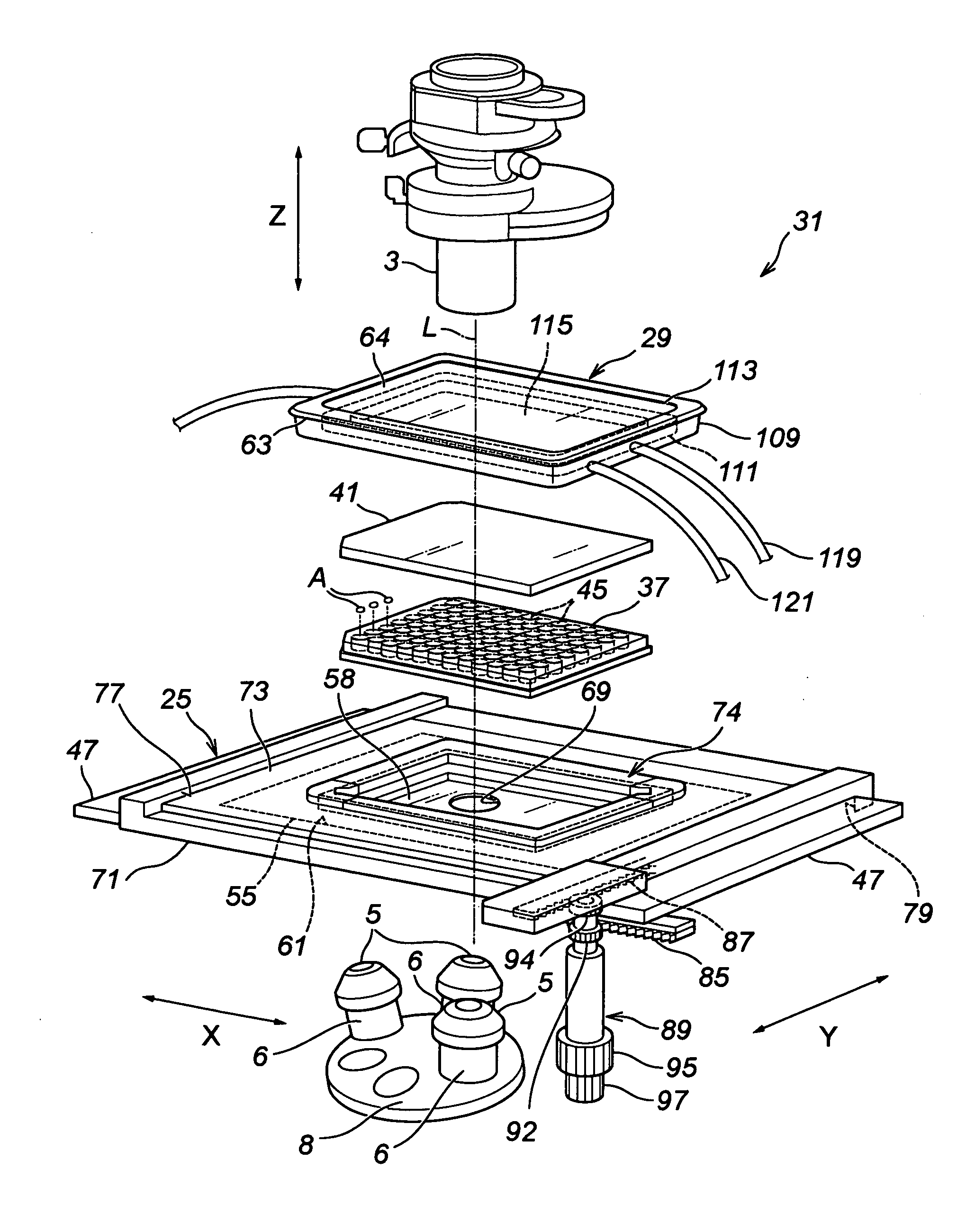
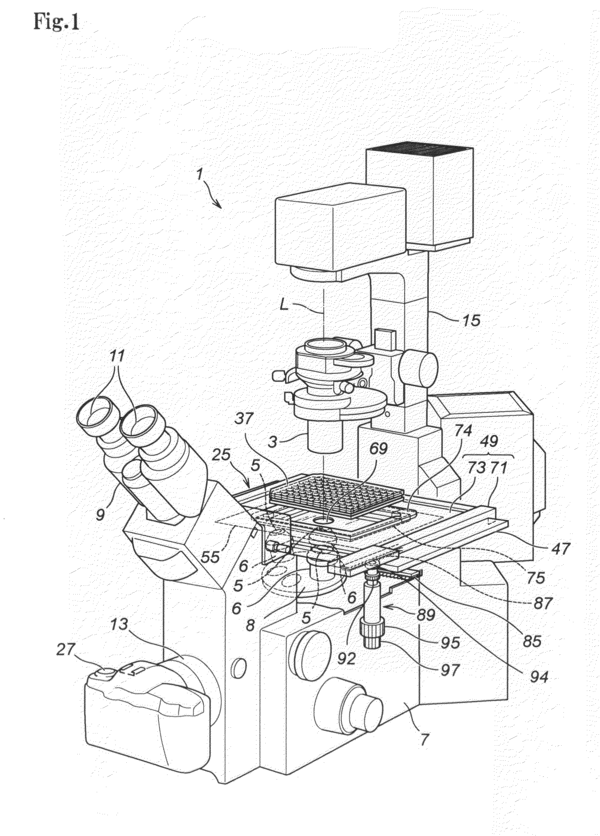
[0128]A best embodiment of a microscope stage and the microscope observing unit according to the present invention will now be described with reference to the attached drawings.

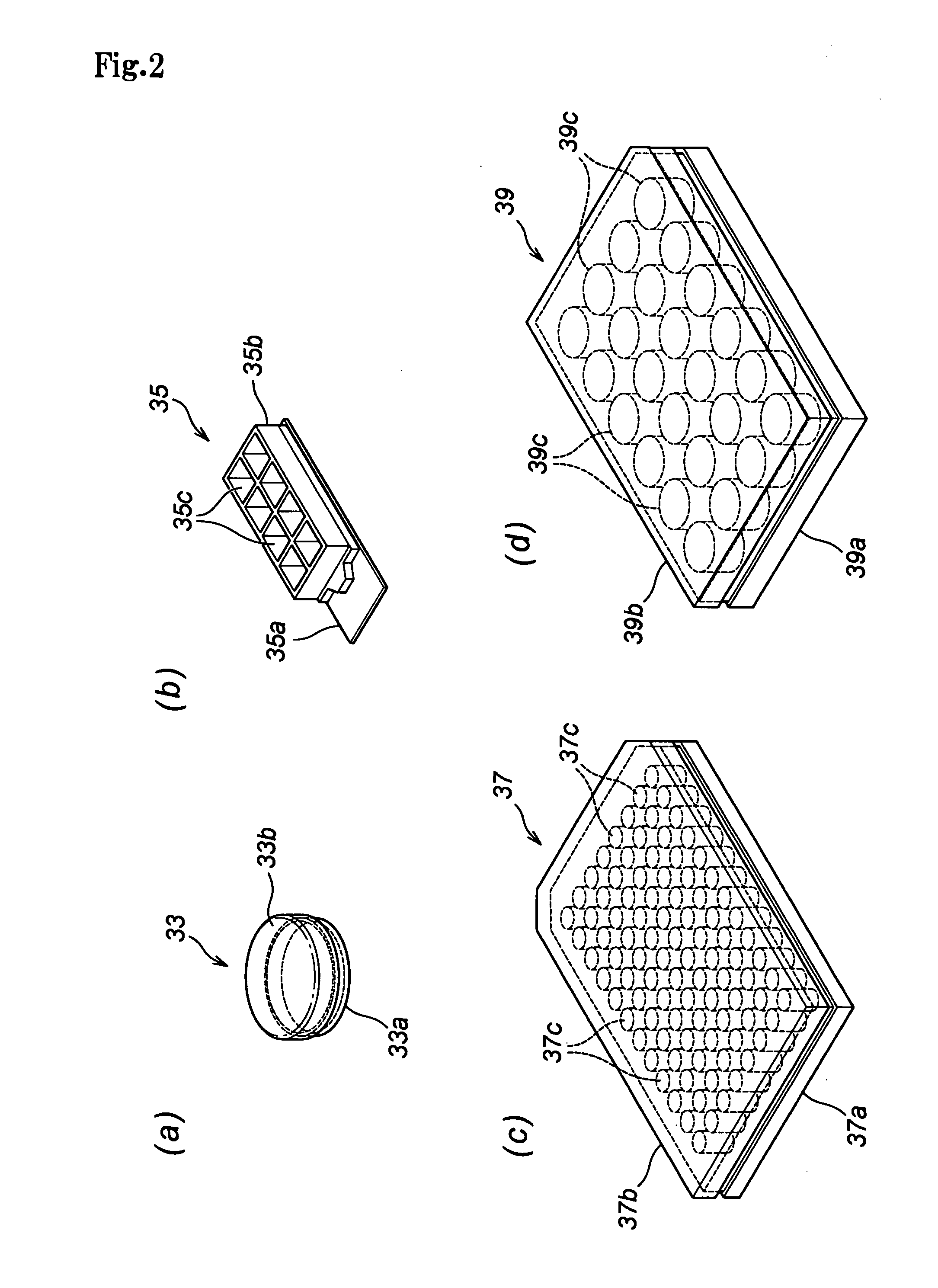
[0129]In the following description, a microscope to which the embodiment of the present invention is to be applied is described in summary, and then vessels for accommodating an object to be observed is described. The microscope stage and the microscope observing unit including the stage will then be described concretely.

[0130]A microscope 1 is provided with a microscope stage 25 of the present invention. Objectives 25 are attached to the end of body tubes 6 and disposed under the stage 25. The three body tubes 6 and the objectives 5 attached thereto different in their magnifying power are supported by a revolving piece 8.

[0131]The microscope 1 further includes binocular tubes 9, eye pieces 11 attached to the tubes 9, and a camera port 13 provided through the front, lower part of the body 7.

[0132]Further, a p...


PUM


Abstract

A microscope stage capable of always heating the entire culture vessel even when the culture vessel is moved in two-dimensional directions, and allowing an object lens and a condenser even in a high-power microscope to approach an object of observation such as a cell until they come into focus. A heating unit (58) faces a well plate (37) on a drive base (49) even when the drive base (49) is driven to any position in two-dimensional directions. Therefore, all the cells A in the small compartments (45) of the well plate (37) are always heated. Since the microscope stage (25) is constituted such that a lower-side base (71) houses an upper-side base (73) and a fixed base (47) in recessed portions, its thickness is considerably small. Accordingly, an object lens (5) and a condenser (3) can approach close to the cells A. Therefore, it is possible for high-power object lens (5) and condenser (3) to focus on the cells A.

Description

FIELD OF THE INVENTION[0001]The present invention relates generally to a microscope stage capable of heating the entire culture vessel containing specimen such as cells or microorganism to be observed, and a microscope observing unit including a microscope stage and a culture device to be disposed on the stage.BACKGROUND OF THE INVENTION[0002]It has been well known in the art to use shallow cylindrical dishes of a diameter of 35 mm as culture vessels for cells or microorganisms. Recently, there have been used culture vessels so called well plates having a number of cells or compartment, each well cells Accommodating a culture solution and cells or microorganisms. The typical dimension of the well plates is of a width of 85 mm and a length of 115 mm. Namely, the well plates are substantially larger than the dishes. The well plates have a variety of depths. As can be seen from above, there has been used culture vessels of various sizes in dependence upon their applications.[0003]When ...

Claims


Application Information

Patent Timeline
IPC IPC(8): G02B21/30
CPCB01L7/00B01L9/523B01L2200/025C12M41/12C12M41/36G02B21/30C12M23/48B01L2300/0829C12M3/00G02B21/00
Inventor TSUCHIYA, HIDEHARU
Owner TOKAI HITKK
Why Eureka
Try Eureka