Liquid optics with folds lens and imaging apparatus

Inactive Publication Date: 2009-06-04
MONUMENT PEAK VENTURES LLC
View PDF68 Cites 70 Cited by
  • Summary
  • Abstract
  • Description
  • Claims
  • Application Information

AI Technical Summary

Benefits of technology

[0007]Liquid lens cells comprise two or more fluids in a chamber. The fluids contact to form a surface that variable by, for example, electrical nodes. A fluid may be, for example, one or more gases, one or more liquids, or a mixture of one or more solids and one or more liquids. Using liquid lens cells to replace one or more moving lens groups results in additional configuration options for the optical path. Replacing moving lens groups with liquid lens cells results in a more compact system. However, a linear optical design may result in a lens that is longer than desired. The use of liquid lens cells instead of a moving group facilitates the use of optical elements such as folds to reduce the physical length of

Problems solved by technology

However, there are intrinsic disadvantages associated in using zoom and focus lens systems with moving lens groups.
In particular, having moving zoom lens groups implies the need for complex mechanically moving parts.
This system complexity may add size, weight and cost and may make the system operation unreliable over a period of time.
These disadvantages together with undesirable limitations, such as a limite

Method used


Image

  • Liquid optics with folds lens and imaging apparatus
  • Liquid optics with folds lens and imaging apparatus
  • Liquid optics with folds lens and imaging apparatus

Examples


Example

[0018]In the following description of preferred embodiments, reference is made to the accompanying drawings that form a part hereof, and in which is shown by way of illustration specific embodiments in which the invention may be practiced. It is to be understood that other embodiments may be utilized and structural changes may be made without departing from the scope of the invention.

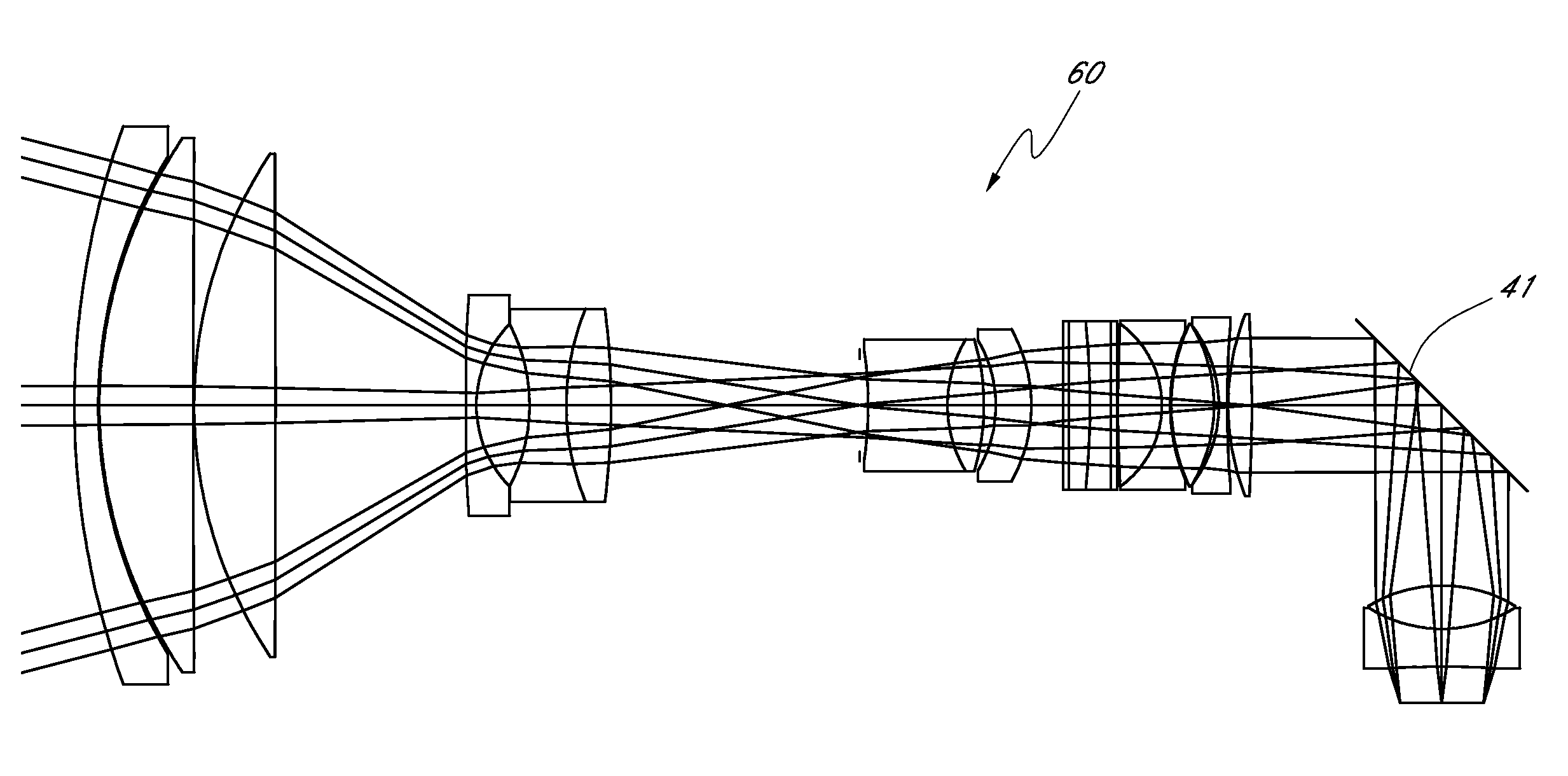
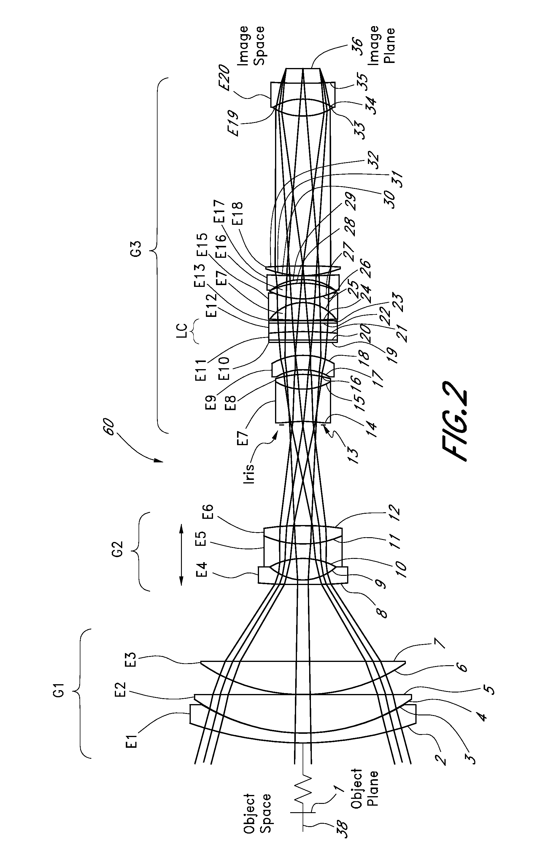
[0019]U.S. Provisional Patent Application No. 60 / 783,338 filed on Oct. 8, 2007 and titled “Liquid Optics Zoom Lens and Imaging Apparatus,” herein incorporated by reference in its entirety, discloses a zoom lens system that employs liquid optics to provide zoom and focus functionality. The use of liquid optics for zooming and focusing provides for alternative lens configurations with redirection of the radiation axis. An exemplary zoom lens system employing liquid optics to provide zoom and focus functionality is described first, followed by embodiments employing redirection of the radiation axis.

Liquid ...


PUM


Abstract

A high performance zoom lens system suitable for use with a camera is disclosed. The zoom lens systems employs redirection of the radiation axis, liquid optics and a movable lens group to provide optical performance over the zoom focal length range at focus distances from close to infinity. The system also provides compensation for undesirable thermally induced effects by adjustments of the zoom group and the variably shaped optical surface in the liquid lens cell.

Description

RELATED APPLICATIONS[0001]This application is related to, and claims the benefit of U.S. Provisional 60 / 992,244 filed Dec. 4, 2007, the entirety of which is hereby incorporated by reference herein and made a part of the present specification.BACKGROUND[0002]1. Field of the Invention[0003]This invention relates to an optical lens system employing liquid optics and redirection of a radiation axis.[0004]2. Description of the Related Art[0005]Imaging applications have historically used two or more movable zoom lens groups to provide zooming and different focal lengths. An additional lens group for focusing may also be needed.[0006]However, there are intrinsic disadvantages associated in using zoom and focus lens systems with moving lens groups. In particular, having moving zoom lens groups implies the need for complex mechanically moving parts. Each movable lens group requires support structures and drive mechanics such as cams and motors and in some cases control electronics to facilit...

Claims


Application Information

Patent Timeline
IPC IPC(8): G02B15/14G02B3/14
CPCG02B3/14G02B7/008G02B15/173G02B13/009G02B15/16G02B13/0075G02B26/004G02B15/143105G02B15/142G02B15/143G03B17/12H04N23/55
Inventor JANNARD, JAMES H.NEIL, IAIN
Owner MONUMENT PEAK VENTURES LLC
Why Eureka
Try Eureka