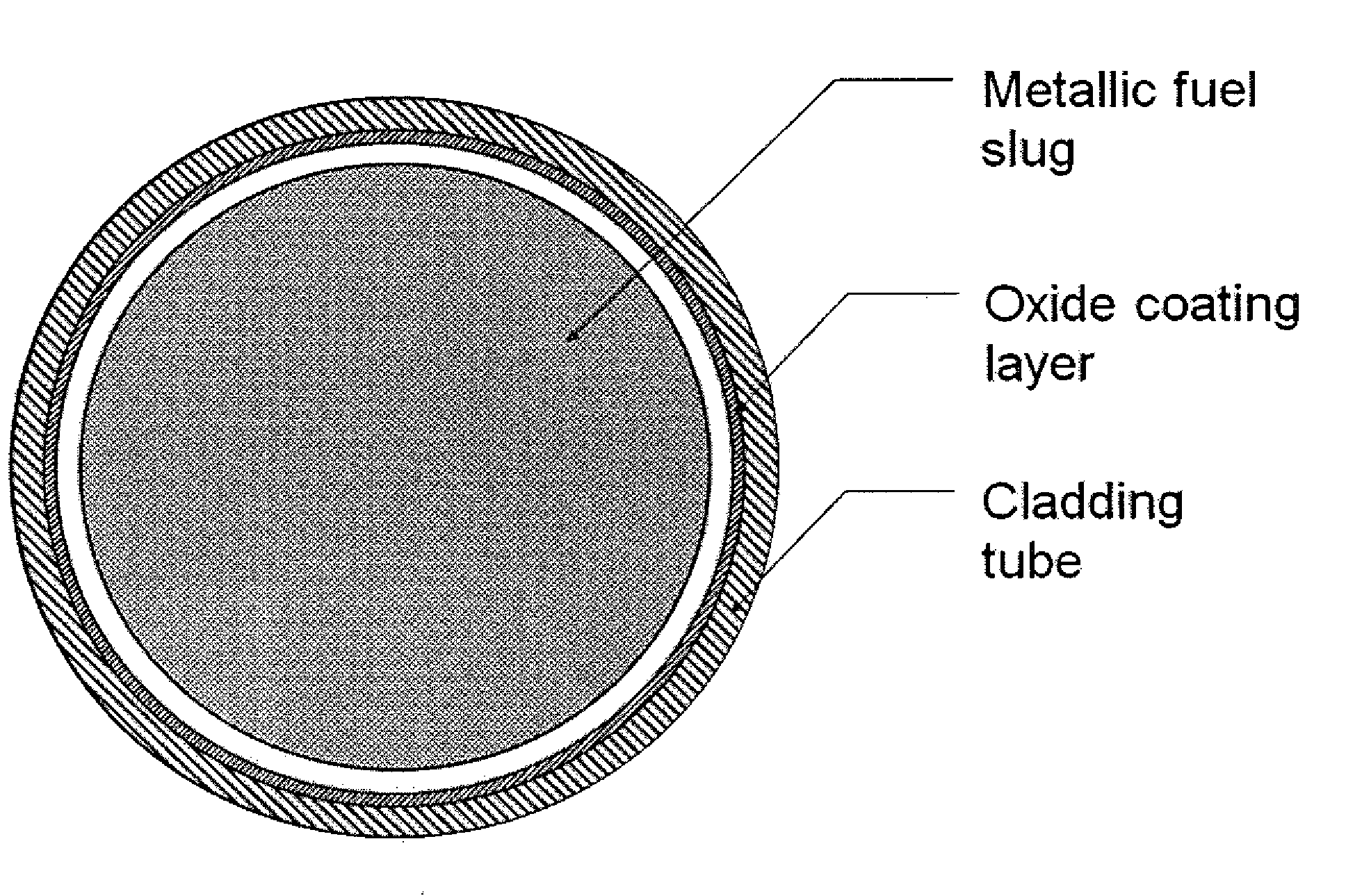
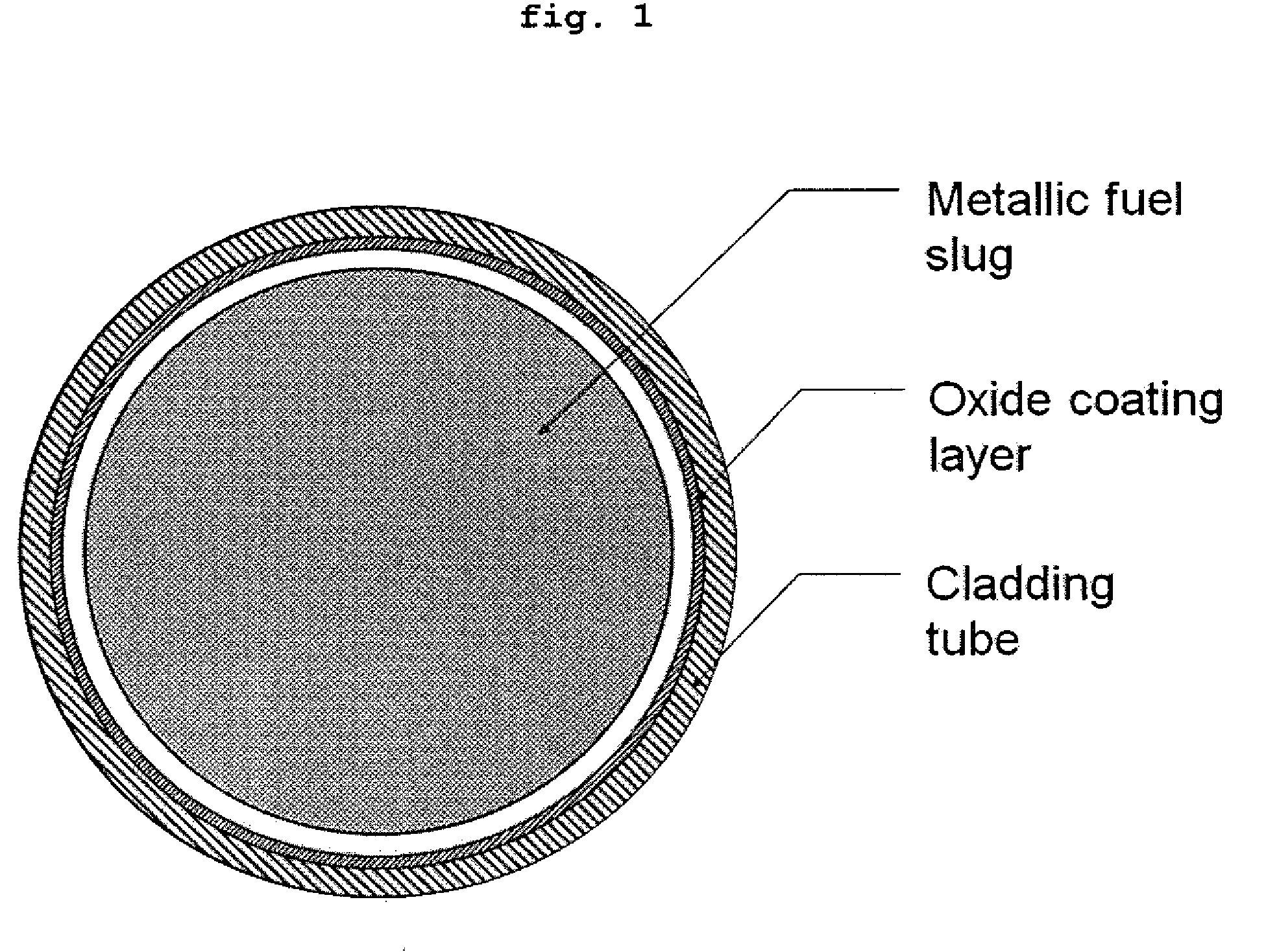
Nuclear fuel rod for fast reactors with oxide coating layer on inner surface of cladding, and manufacturing method thereof

a technology of oxide coating layer and nuclear fuel rod, which is applied in the direction of distance measurement, greenhouse gas reduction, instruments, etc., can solve the problems of cracks in zirconium tubes, significant additional costs, and complicated production of nuclear fuel rods, so as to prolong the fuel life cycle of the fast reactor, increase the maximum permissible burnup, and increase the economic efficiency

Inactive Publication Date: 2009-06-04
KOREA ATOMIC ENERGY RES INST +1
View PDF4 Cites 15 Cited by
  • Summary
  • Abstract
  • Description
  • Claims
  • Application Information

AI Technical Summary

Benefits of technology

[0014]The inventive nuclear fuel rod for fast reactors, which includes the oxide coating layer formed on the inner surface of the cladding tube, can increase the maximum permissible burnup and maximum permissible temperature of metallic nuclear fuel for fast reactors, thus prolonging the fuel lifecycle of the fast reactors ...

Problems solved by technology

The technology of GE has difficulties in that, because the introduction of additional processes is necessary, the production of the nuclear fuel ...

Method used


Image

  • Nuclear fuel rod for fast reactors with oxide coating layer on inner surface of cladding, and manufacturing method thereof
  • Nuclear fuel rod for fast reactors with oxide coating layer on inner surface of cladding, and manufacturing method thereof

Examples


example 1

Manufacture 1 of Nuclear Fuel Rod for Fast Reactors, which has Oxide Coating Layer Formed by Oxidation in Acid Solution

[0032]A stainless steel (SS316L or SS316LN) or ferrite / martensite steel (ASTM Gr. 91 or ASTM Gr. 92) tube for prior nuclear fuel claddings for fast reactors was cut to a length of 100 mm to make a tube sample. Then, the inner surface of the tube was mechanically or chemically polished to have a roughness (Rmax) of less than 1 μm.

[0033]The inner surface of the sample was dipped in a 45-55 vol % nitric acid solution using a specifically designed device at 54° C. for at least 30 minutes according to test procedures specified in ASTM standards (ASTM A967-01, ASTM A380-99, and ASTM B912-00). Then, the sample was washed with distilled water having an impurity concentration of less than 200 ppm, thus manufacturing a nuclear fuel rod for fast reactors having an oxide coating layer formed on the inner surface thereof.

example 2

Manufacture 2 of Nuclear Fuel Rod for Fast Reactors, which has Oxide Coating Layer Formed by Oxidation in Acid Solution

[0034]The procedure of Example 1 was repeated, except that the dipping process was carried out in a 49-60 vol % nitric acid solution at a temperature of 49-60° C. for at least 20 minutes.

example 3

Manufacture 3 of Nuclear Fuel Rod for Fast Reactors, which has Oxide Coating Layer Formed by Oxidation in Acid Solution

[0035]The procedure of Example 1 was repeated, except that the dipping process was carried out in a 20-45 vol % nitric acid solution at a temperature of 21-32° C. for at least 30 minutes.


PUM


Abstract

Disclosed herein are a nuclear fuel rod for fast reactors, which includes an oxide coating layer formed on the inner surface of a cladding, and a manufacturing method thereof. The nuclear fuel rod for fast reactors, which includes the oxide coating layer formed on the inner surface of the cladding, can increase the maximum permissible burnup and maximum permissible temperature of the metallic fuel slug for fast reactors so as to prolong the its lifecycle in the fast reactors, thus increasing economic efficiency. Also, the fuel rod is manufactured in a simpler manner compared to the existing method, in which a metal liner is formed, and the disclosed method enables the cladding of the fuel rod to be manufactured in an easy and cost-effective way.

Description

BACKGROUND OF THE INVENTION[0001]1. Field of the Invention[0002]The present invention relates to a nuclear fuel rod for fast reactors, which includes an oxide coating layer formed on the inner surface of cladding.[0003]2. Description of the Prior Art[0004]Nuclear fuel in fast reactors is designed in various types, including a metallic type, an oxide type, a nitride type and a carbide type, and the nuclear fuel rod includes fissionable fuel slug that undergoes a nuclear reaction. The fissionable fuel slug is sealed by a cladding tube, which is not reactive due to its good compatibility with coolant (e.g. liquid sodium in Sodium-cooled Fast Reactor) and has good heat transfer properties. The fuel rods are assembled at constant intervals to construct a fuel assembly and the assemblies are put into a nuclear reactor core. Herein, the cladding surrounding the nuclear fuel slug should serve to prevent direct contact between the nuclear fuel slug and the coolant, such that chemical interac...

Claims


Application Information

Patent Timeline
IPC IPC(8): G21C3/07
CPCG21C3/20G21Y2002/103G21Y2002/104Y02E30/40G21Y2002/304G21Y2004/10G21Y2004/303G21Y2002/303Y02E30/30G21C3/07G21C3/02
Inventor LEE, CHAN BOCKBAEK, JONG-HYUKLEE, BYOUNG-OONCHEON, JIN-SIKRYU, HO JINKIM, JUN HWANKIM, SUNG HOKIM, TAE-KYUKIM, WOO-GONLEE, CHONG-TAKKIM, KI-HWANKO, YOUNG-MOWOO, YOON-MYEONGOH, SEOK-JINHAHN, DOHEE
Owner KOREA ATOMIC ENERGY RES INST
Why Eureka
Try Eureka