

Electro-dynamic transducer with a slim form factor
a transducer and slim technology, applied in the direction of transducer details, electrical transducers, electrical apparatus, etc., can solve the problems of low resonance frequency, flat speaker design, and small distance between suspension points, and achieve satisfactory stability and low resonance frequency
- Summary
- Abstract
- Description
- Claims
- Application Information
AI Technical Summary
Benefits of technology
Problems solved by technology
Method used
Image

Examples
Embodiment Construction
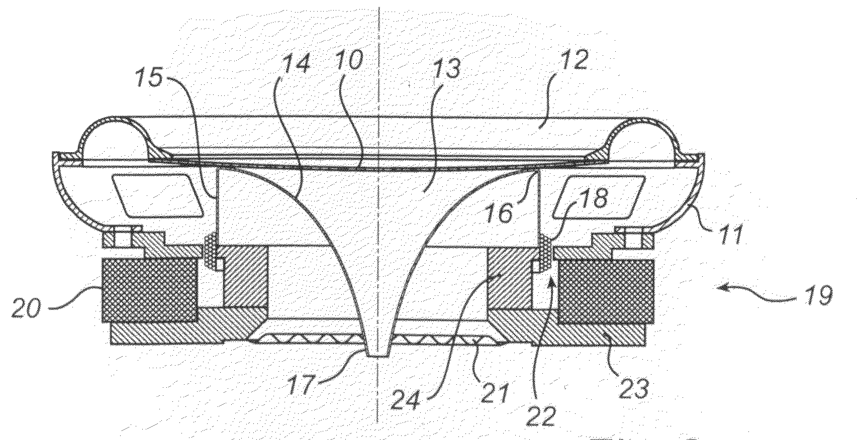
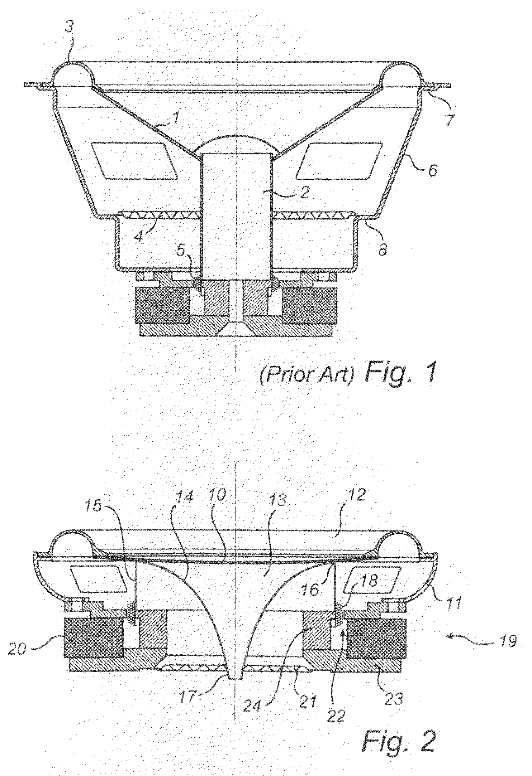
[0026]FIG. 2 shows a schematic cross section of a transducer according to a first embodiment of the invention. A diaphragm 10 is suspended in a basket enclosure 11 by a suspension 12 around its perimeter. The suspension may be e.g. a corrugated rubber annular rim. The back side (facing the interior of the loudspeaker) is attached to a coil former 13.
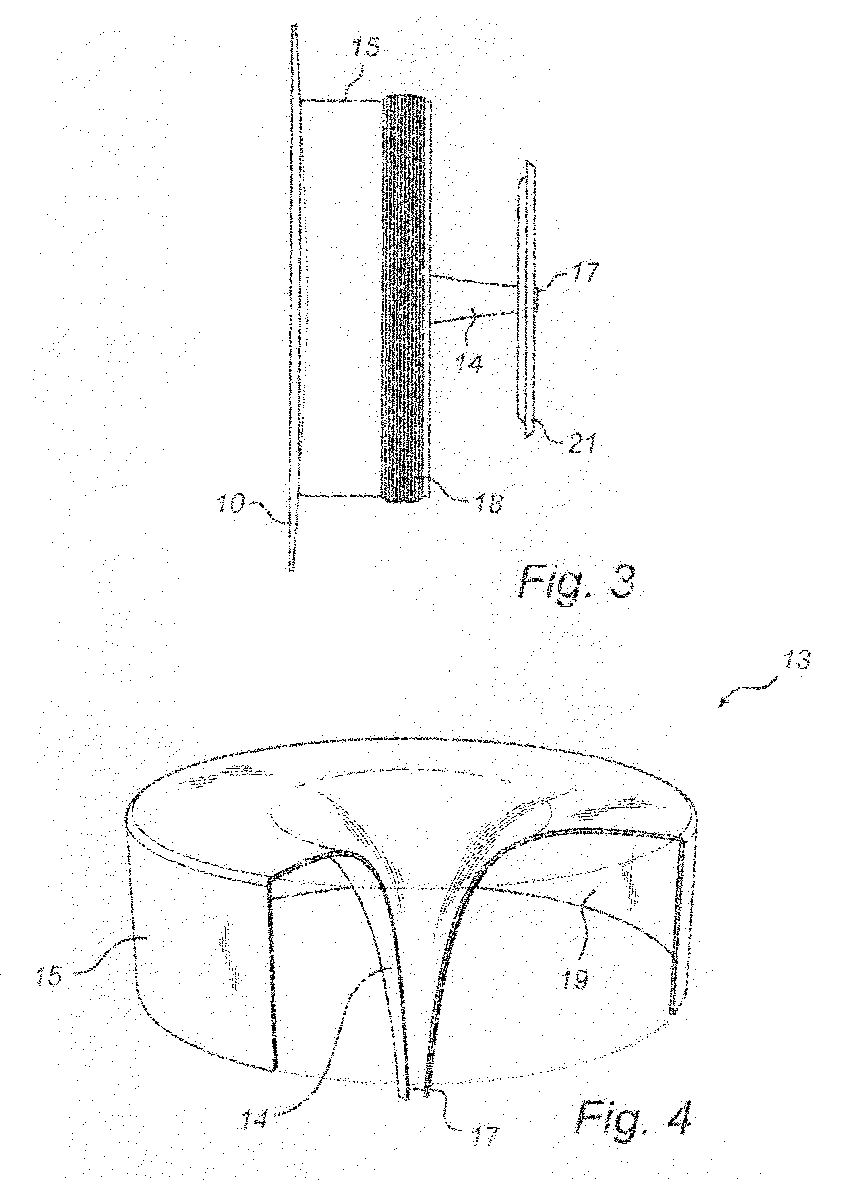
[0027]The coil former has two portions 14 and 15, arranged coaxially in relation to each other. In the illustrated embodiment, the first, inner portion 14 is shaped as a hyperbolic cone, and extends from an annular attachment 16 to the diaphragm to form a tapered end 17 at a distance from the diaphragm. The second, outer portion also extends from the annular attachment 16 and is essentially cylindrical in shape. The length of the inner portion is greater than, here approximately twice, the length of the outer portion.
[0028]A coil 18 is arranged around the periphery of the second coil former portion 15, and surrounded by a magnetic system...
PUM
 Abstract
Description
Claims
Application Information