Carbon Fiber Warming System for Fiber Composite Gas Storage Cylinders

a warming system and carbon fiber technology, applied in the field of heating systems, can solve the problems of storage gas leakage, adverse mechanical stress effects, decompression of the tank, etc., and achieve the effects of reducing the risk of fuel gas leakage, reducing overall system temperature differences, and increasing tank durability

Inactive Publication Date: 2009-06-04
HONDA MOTOR CO LTD
View PDF19 Cites 12 Cited by
  • Summary
  • Abstract
  • Description
  • Claims
  • Application Information

AI Technical Summary

Benefits of technology

The present invention provides a way to heat up a car's engine quickly when it starts in very hot or very cool weather. This helps prevent damage to the engine from starting too slowly or getting damaged due to extreme temperatures. By doing this, drivers can always have reliable performance no matter what kind of season they're facing.

Problems solved by technology

The technical problem addressed in this patent text is the potential for low temperatures in the tank system of vehicles powered by compressed natural gas or hydrogen gas, which can lead to damage to the seals and flow controls in the tank system and cause the stored gas to leak. This problem is caused by the tank pressure decreasing when gas is consumed by the vehicle power plant during driving, and the gas absorbing materials in the tank interior absorbing the intrinsic heat in the gas. In cold climates, the internal gas temperature in the tank can drop to a temperature that is below the permissible operating temperature of the seals and flow controls, causing damage to the tank system assembly.

Method used


Image

  • Carbon Fiber Warming System for Fiber Composite Gas Storage Cylinders
  • Carbon Fiber Warming System for Fiber Composite Gas Storage Cylinders
  • Carbon Fiber Warming System for Fiber Composite Gas Storage Cylinders

Examples


Embodiment Construction

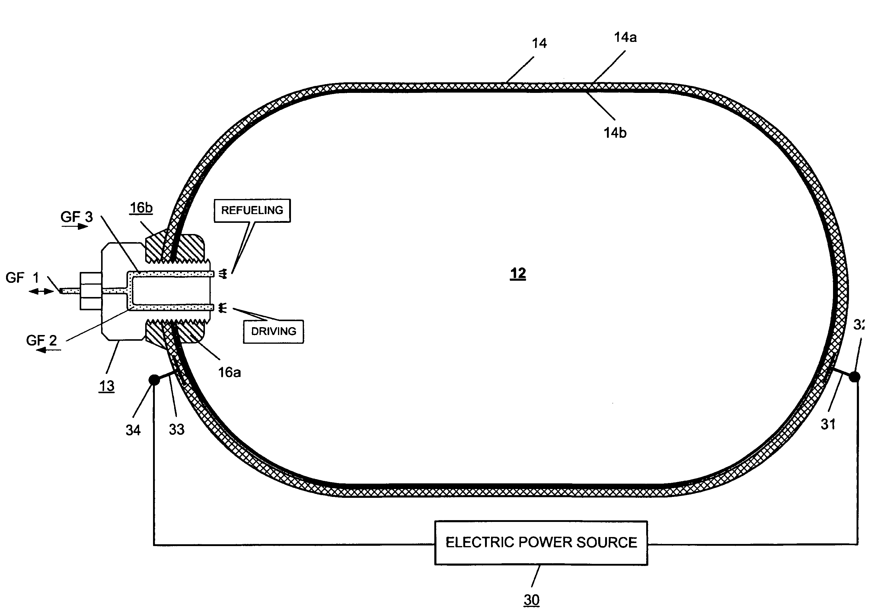
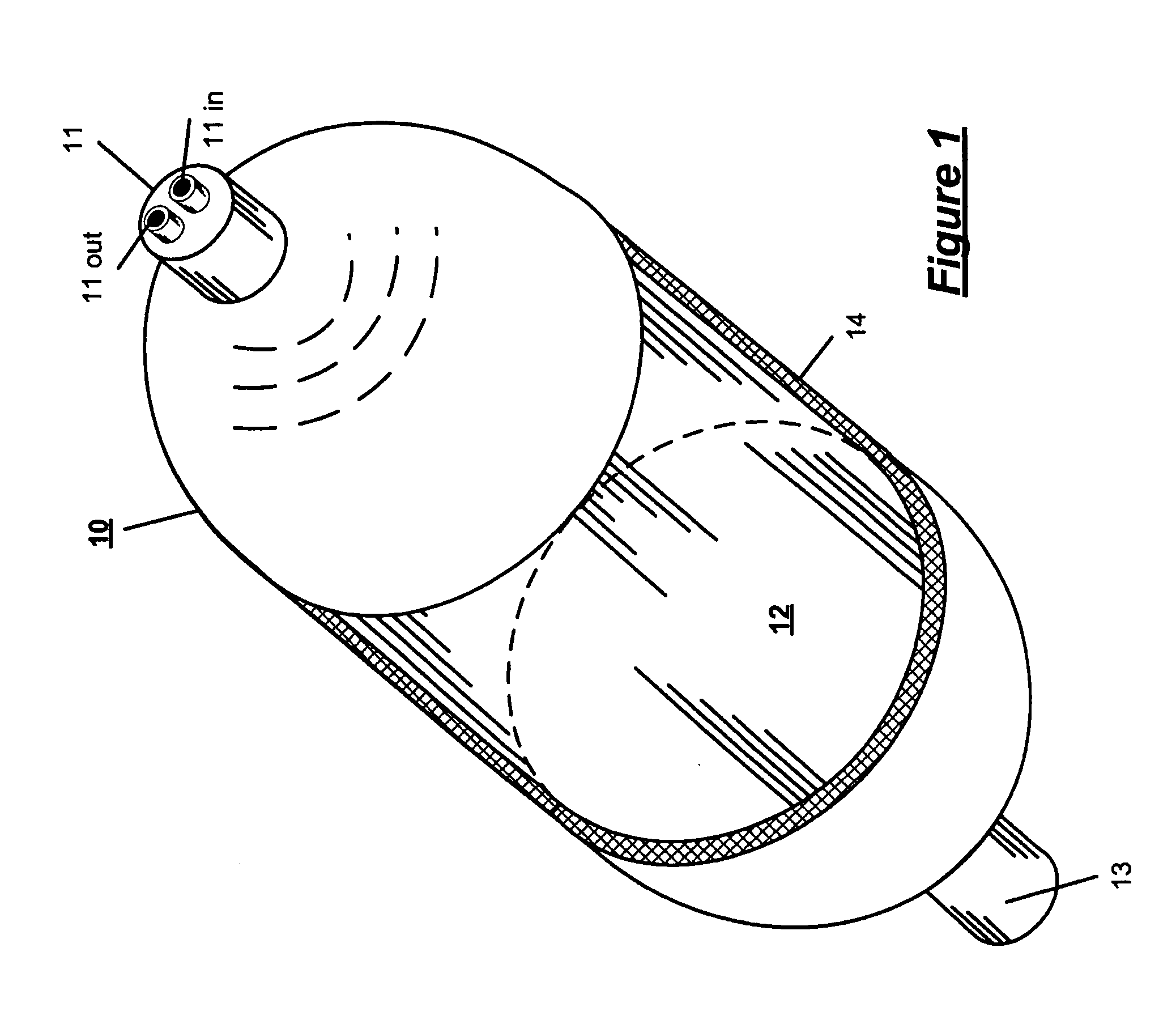
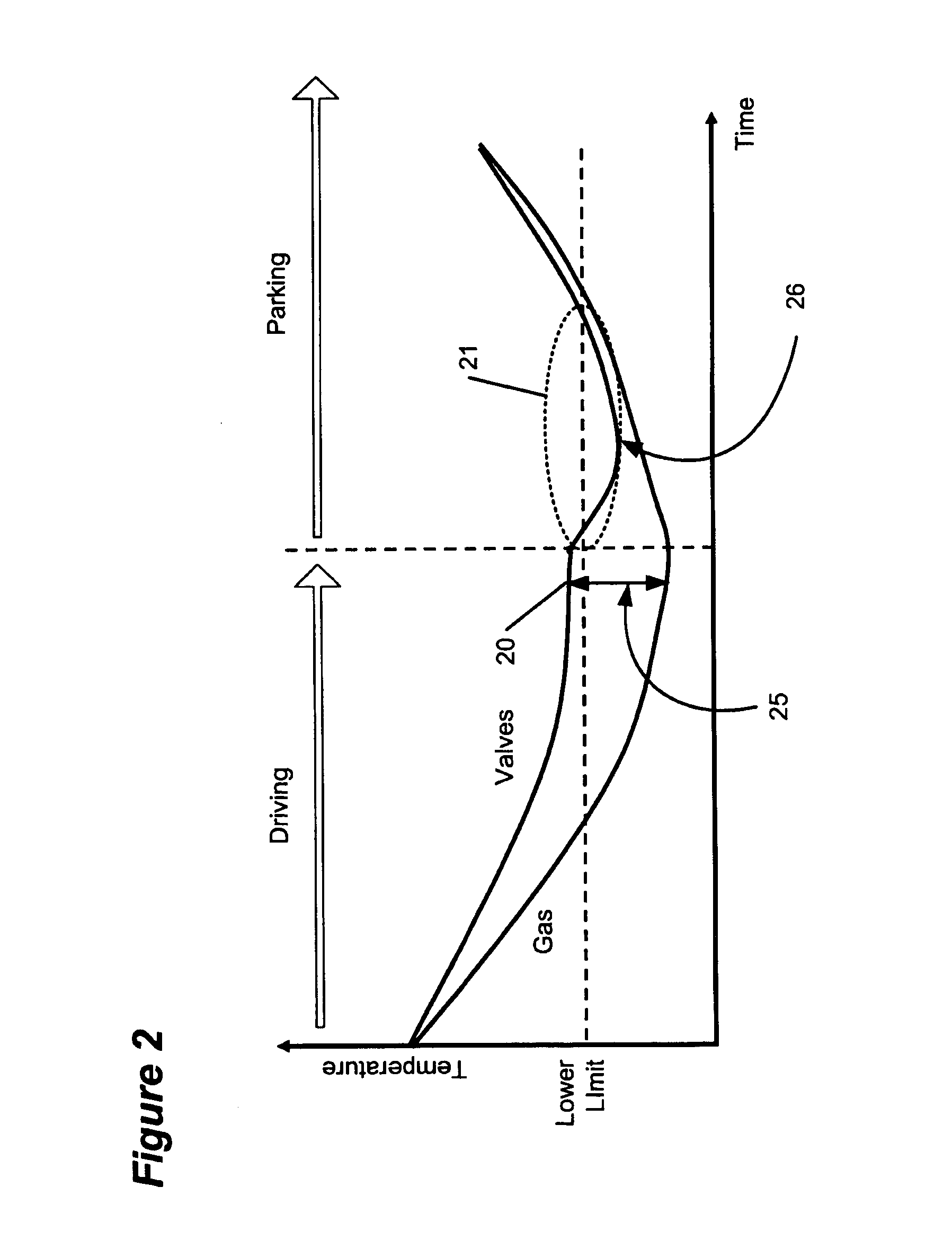
[0014]In brief, the invention provides a warming system for high pressure gas storage tanks utilized on high pressure gas fueled vehicles including vehicles powered by compressed natural gas, CNG, and fuel cell and internal combustion engines powered by hydrogen gas. In many examples, such vehicles include gas fuel tanks that may include gas absorbing materials in the interior of the tank. During driving, the gas cools because a decrease in the tank pressure occurs. When a vehicle tank includes gas absorbing materials, the gas absorbing materials absorb heat during the gas discharge from the tank further contributing to the cooling effect. Environmentally, a typical ambient temperature is approximately 20° C. In cold climates, the internal gas temperature in a vehicle tank can drop to −60° C. or below, a temperature that may be below the permissible operating temperature range of O-ring and / or other rubber or polymer seals used in the tank and the port inlet and outlet metal part as...


PUM

PropertyMeasurementUnit
Electrical resistanceaaaaaaaaaa
Temperatureaaaaaaaaaa

Abstract

A heating system for a fiber composite high pressure gas storage tank for maintaining the temperature of the gas within the tank and the gas flow components associated with one or more boss at the tank ends above the lower design tolerance limit for the tank and flow control assembly, wherein the tank is formed from a polymeric binder having embedded therein longitudinally extending conductive and resistive fiber material strands, comprising an electric power source interconnected with the conductive and resistive tank wall whereby the fibers in the tank wall comprise a heater for warming the tank system such that the temperature of the components associated with the tank assembly does not drop below the lower tolerance temperature limit of the tank assembly.

Description


Claims


Application Information

Patent Timeline
Owner HONDA MOTOR CO LTD
Why Eureka
Try Eureka