
System and method for three-dimensional schematic capture and result visualization of multi-physics system models

a multi-physics system and schematic capture technology, applied in the field of simulation of the physical behavior of multi-physics systems, can solve the problems of time-consuming process and inability to use the mems device by itsel

Active Publication Date: 2009-06-04
COVENTOR
View PDF5 Cites 62 Cited by
  • Summary
  • Abstract
  • Description
  • Claims
  • Application Information

AI Technical Summary

Problems solved by technology

Attributes of CAD / CAE tools and EDA tools must be combined to design and simulate virtual models of multi-physics devices such as Micro Electro-Mechanical Systems (MEMS) devices prior to beginning the costly and time-consuming process of fabricating the actual physical devices.
Typically, MEMS devices are not useful by themselves.

Method used


Image

  • System and method for three-dimensional schematic capture and result visualization of multi-physics system models
  • System and method for three-dimensional schematic capture and result visualization of multi-physics system models
  • System and method for three-dimensional schematic capture and result visualization of multi-physics system models

Examples


Embodiment Construction

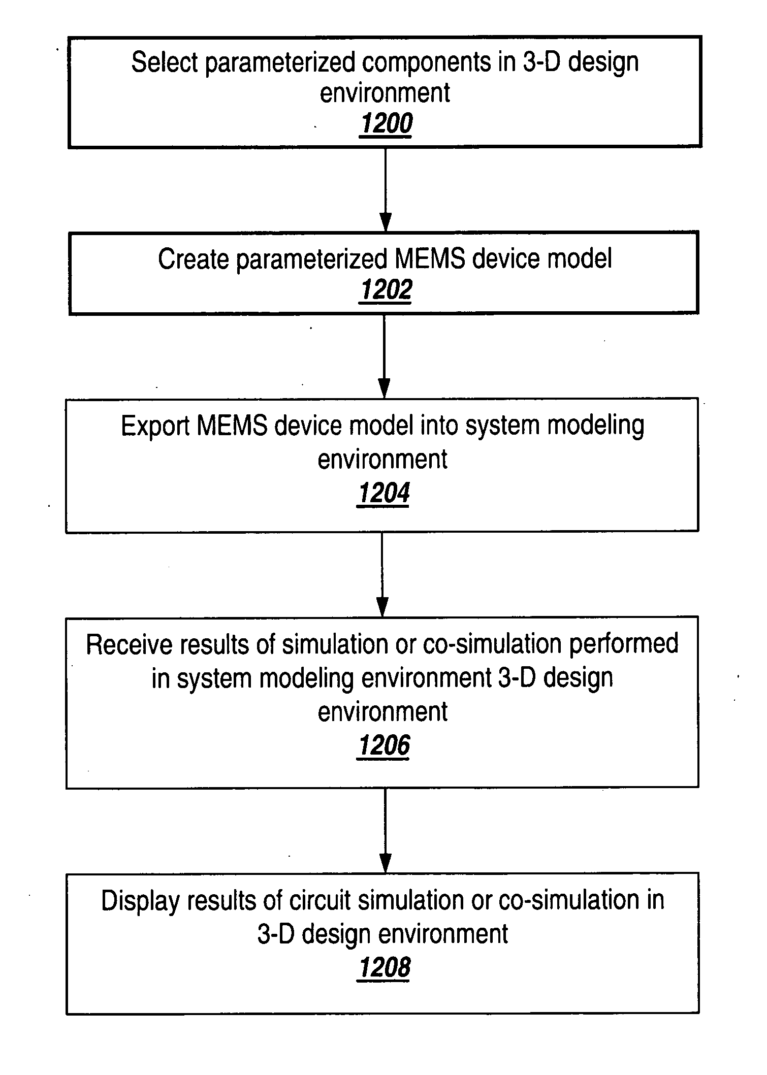
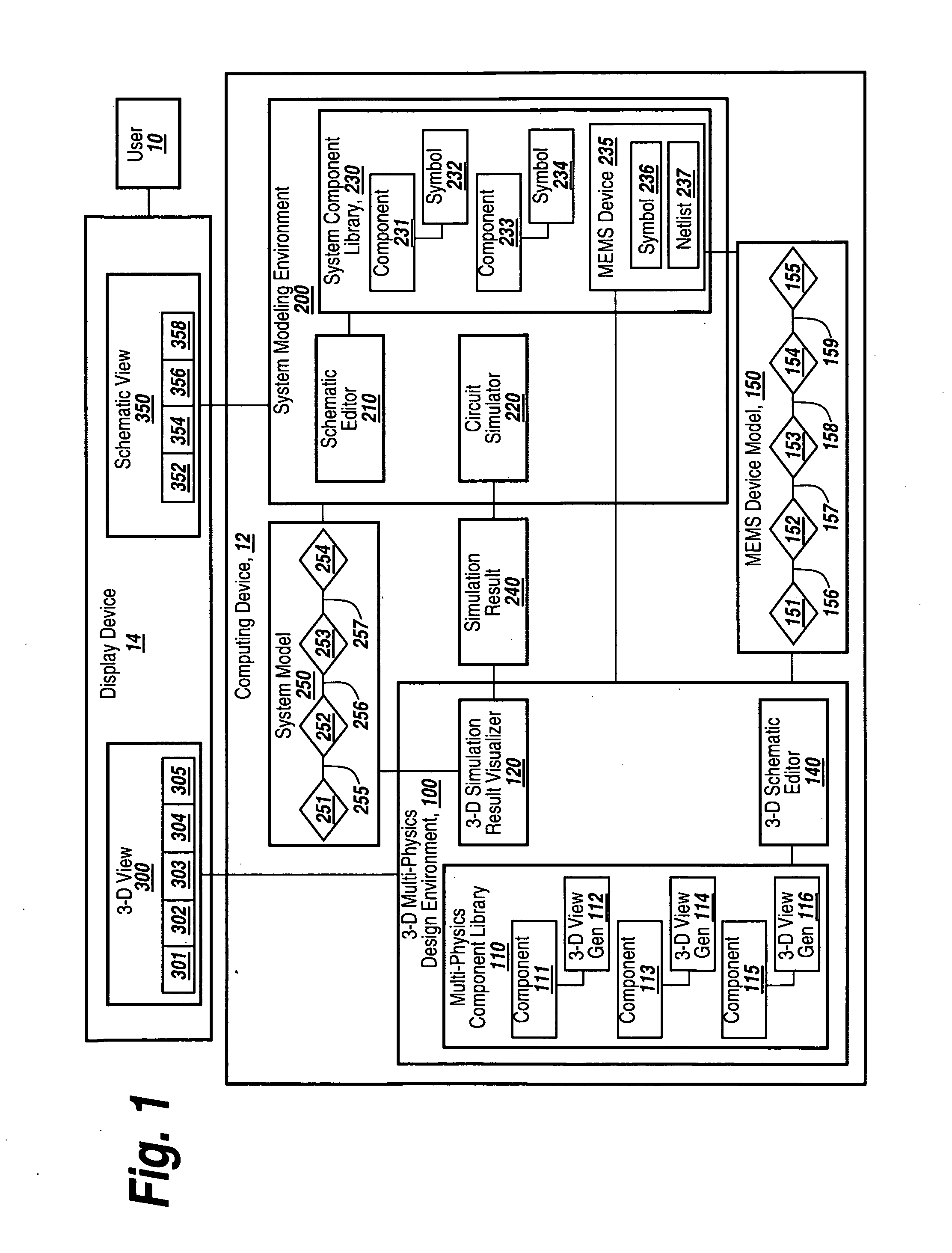
[0027]The embodiments of the present invention enable the creation of a multi-physics device model, such as a MEMS device model, in a three-dimensional (3-D) design environment that is integrated with a system modeling environment. The created device model differs from a model created in a typical feature-based 3-D CAD modeling tool in that there is an underlying behavioral model associated with each component of the created device model. The created device model may be exported to a system modeling environment where it can be integrated into a schematic design and used in performing a circuit simulation or co-simulation. The behavioral model for the created device may be parameterized with respect to manufacturing and design dependent variables such as material properties and dimensional variations, as well as geometric properties of the design. The results of system-level simulations or co-simulations performed in the system modeling environment can subsequently be loaded back int...


PUM


Abstract

A 3-D multi-physics design environment (“3-D design environment”) for designing and simulating multi-physics devices such as MEMS devices is discussed. The 3-D design environment is programmatically integrated with a system modeling environment that is suitable for system-level design and simulation of analog-signal ICs, mixed-signal ICs and multi-physics systems. A parameterized MEMS device model is created in a 3-D graphical view in the 3-D design environment using parameterized model components that are each associated with an underlying behavioral model. After the MEMS device model is completed, it may be exported to a system modeling environment without subjecting the model to preliminary finite element meshing.

Description

RELATED APPLICATION [0001]This application claims the benefit of a U.S. provisional patent Application entitled “A System and Method for Three-Dimensional Schematic Capture and Result Visualization of Multi-Physics System Models”, Application No. 60 / 991249, filed on Nov. 30, 2007.FIELD OF THE INVENTION [0002]The embodiments of the present invention relate generally to simulating the physical behavior of multi-physics systems and more particularly to the creation of a parameterized behavioral model for a multi-physics device in a three-dimensional (3-D) design environment and the subsequent use of the created model in the 3-D design environment and an integrated system modeling environment.BACKGROUND [0003]Computer Aided Design (CAD) and Computer Aided Engineering (CAE) tools are used, respectively, to design and simulate virtual models of mechanical devices prior to producing actual physical devices. Similarly, Electronic Design Automation (EDA) tools are used to design and simulate...

Claims


Application Information

Patent Timeline
IPC IPC(8): G06F17/50
CPCG06F2217/74G06F2217/02G06F17/5086G06F2217/86G06F2217/66G06F17/5045G06F17/5009G06F17/5022G06F2111/20G06F30/30G06F30/33G06F30/17G06F2115/08G06F2111/12G06F2117/08G06F30/20G06F2115/04G06F30/3308
Inventor LORENZ, GUNARKAMON, MATTAN
Owner COVENTOR
Learn More