Variable friction hinge

Inactive Publication Date: 2009-06-11
SHIN ZU SHING
View PDF11 Cites 7 Cited by
  • Summary
  • Abstract
  • Description
  • Claims
  • Application Information

AI Technical Summary

Benefits of technology

[0006]The main objective of the present invention is to provide a variable friction hinge to allow a cover of an electronic device to have different opening and closing resistances. The hinge with variable friction is mounted between the cover and the base of the electronic device and has a pintle, a stationary leaf and a washer assembly. The pintle is connected to the cover. The stationary leaf is connected to the base and has an activating panel with an activating edge. The washer assembly has a movable washer

Problems solved by technology

When the cover is closed relative to the base, the hinge needs to offer more resistance to prevent the cover from gaining momentum and bumping into the base, thereby causing damage.
However, the conventional hi

Method used


Image

  • Variable friction hinge
  • Variable friction hinge
  • Variable friction hinge

Examples


Embodiment Construction

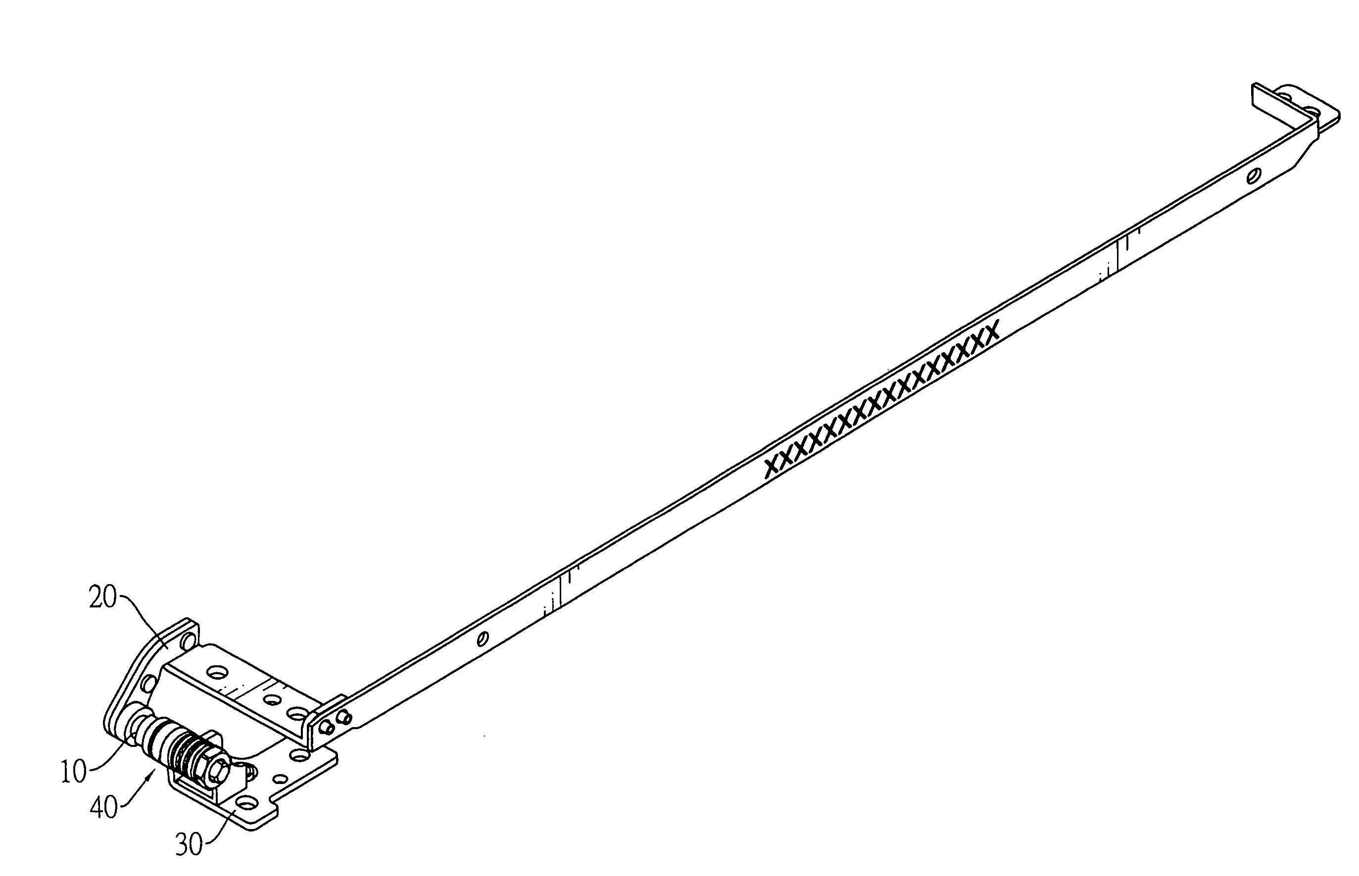
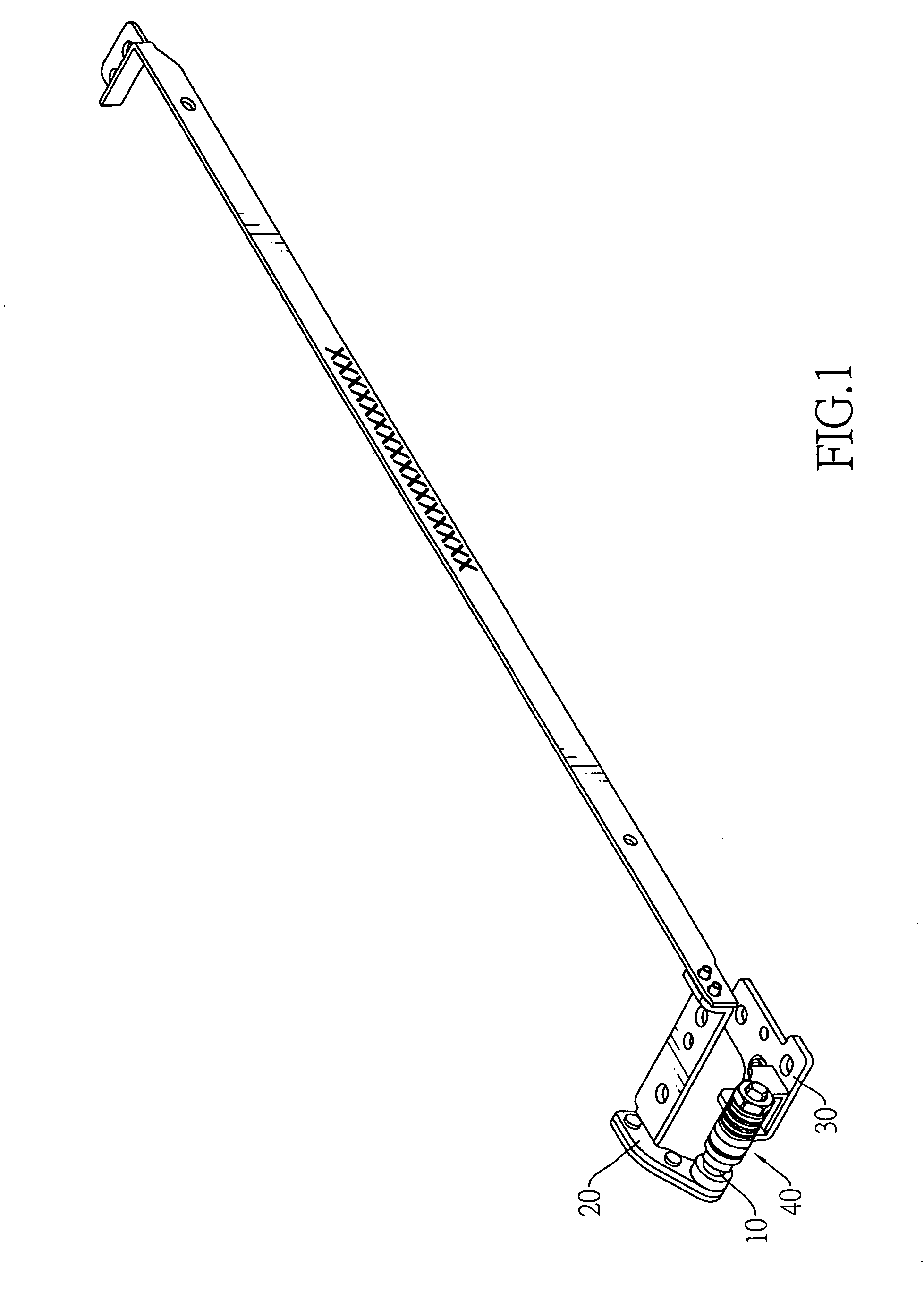
[0013]With reference to FIG. 1, a variable friction hinge in accordance with the present invention comprises a pintle (10), an optional rotating leaf (20), a stationary leaf (30) and a washer assembly (40).

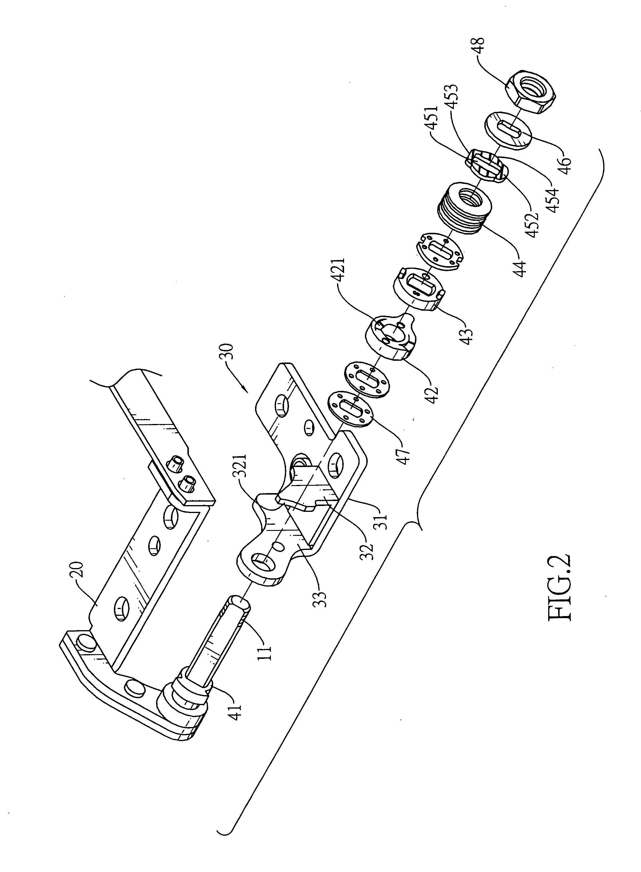
[0014]With further reference to FIG. 2, the pintle (10) is non-circular in cross section and has a proximal end, a distal end and an optional threaded segment (11). The threaded segment (11) is formed around the distal end of the pintle (10).

[0015]The rotating leaf (20) is attached securely to the proximal end of the pintle (10).

[0016]With further reference to FIG. 3, the stationary leaf (30) is connected to the pintle (10) and has a main panel (31), an activating panel (32) and a mounting panel (33). The activating panel (32) is formed perpendicularly on the main panel (31) and has an activating edge (321) and an outer surface. The mounting panel (33) is formed perpendicularly on the main panel (31) near the outer surface of the activating panel (32), is mounted rotatably around ...


PUM


Abstract

A variable friction hinge is mounted between a cover and a base of an electronic device and has a pintle, a stationary leaf and a washer assembly. The pintle is connected to the cover. The stationary leaf is connected to the base and has an activating panel with an activating edge. The washer assembly has a movable washer, an abrasion washer and a biasing member. The movable washer selectively abuts the activating edge of the activating panel and has an elongated hole slidably mounted securely around the pintle. The movable and the abrasion washers have teeth corresponding to and selectively engaging each other, causing less friction when engaged and more friction when disengaged. When rotated the movable washer selectively disengages the teeth causing the hinge to have greater friction when being rotated one way than the other.

Description

BACKGROUND OF THE INVENTION[0001]1. Field of the Invention[0002]The present invention relates to a hinge, especially to a variable friction hinge being mounted between a cover and a base of an electronic device to provide different friction when the cover is opened or closed.[0003]2. Description of the Prior Arts[0004]Electronic devices such as notebook computers, cell phones and the like have a cover with a display and a base. To allow the cover to be pivoted relative to the base, a hinge is mounted between the cover and the base. The hinge provides friction when the cover is pivoted to the base to maintain the cover at any desired angle. When the cover is closed relative to the base, the hinge needs to offer more resistance to prevent the cover from gaining momentum and bumping into the base, thereby causing damage. When the cover is opened relative to the base, the hinge needs to offer less resistance to allow the cover to be opened quickly and easily and give access to the elect...

Claims


Application Information

Patent Timeline
IPC IPC(8): E05F1/08
CPCE05D11/087E05Y2900/606G06F1/1616Y10T16/5398Y10T16/54038Y10T16/538Y10T16/5403G06F1/1681
Inventor CHEN, PO-CHUAN
Owner SHIN ZU SHING
Why Eureka
Try Eureka