Misfire determination device and method for internal combustion engine, and vehicle including misfire determination device

Active Publication Date: 2009-06-11
TOYOTA JIDOSHA KK
View PDF14 Cites 27 Cited by
  • Summary
  • Abstract
  • Description
  • Claims
  • Application Information

AI Technical Summary

Benefits of technology

[0020]The above configuration also brings about the effects brought about by the above internal-combustion-engine misfire determination device, that is, it is possible to accurately determine the occurrence of a misfire in the internal combustion engine even when resonance due to torsion of the torsion element occurs, and it is also possible to reduce the influence of the delay due to communication on the accuracy in determining the occurrence of a misfire in the internal combustion engine based on the output shaft rotational speed and the downstream shaft rotational speed when at least one of the output shaft rotational speed and the downstream side shaft rotational speed is acquired via the communication.
[0021]The vehicle according to this aspect may further include an electric motor that outputs mechanical power to the downstream-side shaft downstream of the torsion element, and the downstream shaft rotational speed detection portion may detect an electric motor rotational speed that is the rotational speed of the electric motor, and convert the detected electric motor rotational speed to obtain the downstream shaft rotational speed. With the above configuration, it is possible to use the high precision sensor for detecting the rotational speed of the electric motor as the downstream shaft rotational speed detection portion. In addition, it is possible to accurately d

Problems solved by technology

As a result, even when it is tried to detect the occurrence of a misfire in one of the cylinders of the engine

Method used


Image

  • Misfire determination device and method for internal combustion engine, and vehicle including misfire determination device
  • Misfire determination device and method for internal combustion engine, and vehicle including misfire determination device
  • Misfire determination device and method for internal combustion engine, and vehicle including misfire determination device

Examples


Embodiment Construction

[0040]Modes for carrying out the invention will be described below using embodiments.

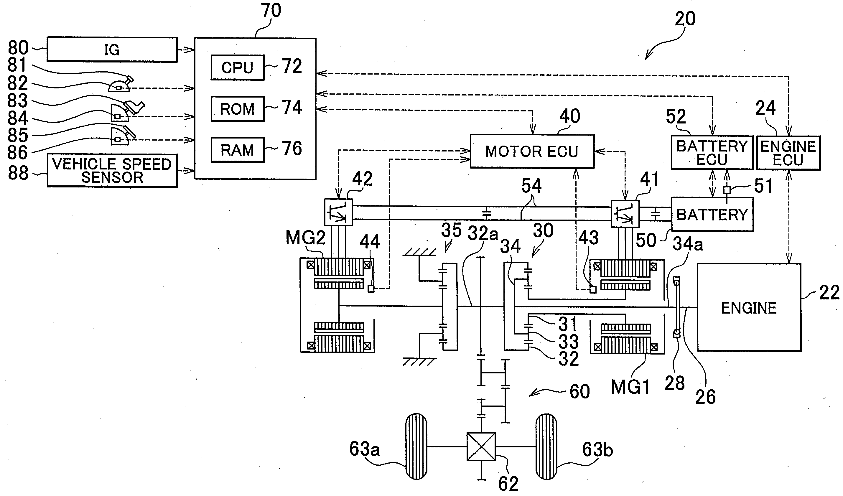
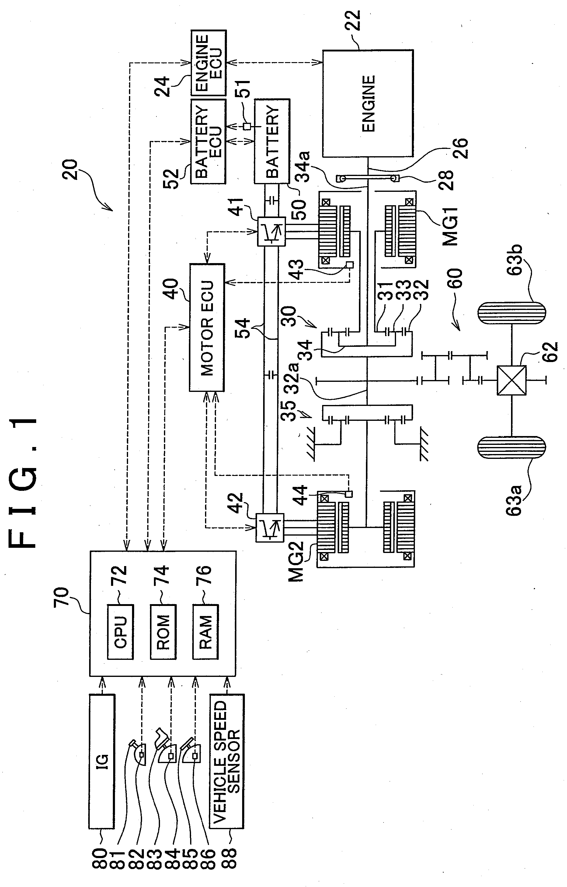
[0041]FIG. 1 is a configuration diagram showing an outline of a configuration of a hybrid car 20 in which an internal-combustion-engine misfire determination device is installed, according to an embodiment of the invention. As shown in FIG. 1, the hybrid car 20 of this embodiment includes: an engine 22, a three-axis power distribution / integration mechanism 30 that is connected to a crankshaft 26, which serves as an output shaft of the engine 22, through a damper 28, which serves as a torsion element; a motor MG1 capable of generating electricity that is connected to the power distribution / integration mechanism 30; a speed reduction gear 35 fixed to a ring gear shaft 32a that is connected to the power distribution / integration mechanism 30; a motor MG2 connected to the speed reduction gear 35; and an electronic control unit 70 for a hybrid system (hereinafter referred to as the hybrid ECU 70), which c...


PUM


Abstract

A misfire determination device for a multi-cylinder internal combustion engine, of which an output shaft is connected, through a torsion element, to a downstream shaft downstream of the torsion element, includes: an first portion for detecting an output shaft rotational speed that is the rotational speed of the output shaft; a second portion for detecting a downstream shaft rotational speed that is the rotational speed of the downstream shaft; a third portion that calculates a component caused by an influence of resonance due to torsion of the torsion element on the output shaft rotational speed, based on the acquired output shaft rotational speed and the acquired downstream shaft rotational speed; and a fourth portion for determining the occurrence of the misfire in the internal combustion engine based on a rotational speed that is obtained by subtracting the calculated component from the detected output shaft rotational speed.

Description

INCORPORATION BY REFERENCE[0001]The disclosures of Japanese Patent Application No. 2007-319329 filed on Dec. 11, 2007 and Japanese Patent Application No. 2008-191398 filed on Jul. 24, 2008 including the specifications, drawings and abstracts are incorporated herein by reference in their entirety.BACKGROUND OF THE INVENTION[0002]1. Field of the Invention[0003]The invention relates to an internal-combustion-engine misfire determination device and method, and to a vehicle including the device, and more specifically, to an internal-combustion-engine misfire determination device and method that determine the occurrence of a misfire in a multi-cylinder internal combustion engine, of which an output shaft is connected, through a torsion element, to a downstream shaft downstream of the torsion element, and to a vehicle including such a misfire determination device.[0004]2. Description of the Related Art[0005]As this kind of misfire determination device, a device has been proposed that, in a...

Claims


Application Information

Patent Timeline
IPC IPC(8): G01M15/11
CPCG01M15/11
Inventor SUZUKI, TAKASHI
Owner TOYOTA JIDOSHA KK
Why Eureka
Try Eureka