Shock absorber

a technology of shock absorber and shock absorber, which is applied in the direction of shock absorber, vibration damper, spring/damper, etc., can solve the problems of shock absorber not being able to control the damping force characteristics in response, deterioration of driving comfort, and inability to ensure vehicle stability, etc., to reduce the damping force

Inactive Publication Date: 2009-06-11
HL MANDO CORP
View PDF12 Cites 29 Cited by
  • Summary
  • Abstract
  • Description
  • Claims
  • Application Information

AI Technical Summary

Benefits of technology

[0013]According to one aspect a shock absorber is provided that includes a floating piston disposed within a hollow chamber of a piston rod to reduce a damping force and can significantly reduce the damping force in a section where the piston rod moves repetitiously.

Problems solved by technology

Therefore, a low damping force characteristic can improve driving comfort but does not ensure stability of the vehicle, whereas a high damping force characteristic can maintain the stable posture of the vehicle but entails deterioration of driving comfort.
As such, the conventional shock absorber is incapable of controlling damping force characteristics in response to variation of the road state or the posture of the vehicle.
However, the hollow chamber 20 has a restricted size so that a range of motion of the floating piston 22 is limited, thereby providing a low effect in reduction of the damping force.
Further, when increasing the size of the hollow chamber 20 to improve the effect of reducing the damping force, there are problems of a manufacturing cost increase and a durability deterioration of the piston rod 14.
Additionally, the conventional shock absorber undergoes friction between the outer surface of the floating piston and the inner surface of the hollow chamber while the floating piston moves up and down within the hollow chamber to cause an inefficient initial movement and a stick slip phenomenon between the floating piston and the hollow chamber, thereby lowering driving comfort.
Furthermore, when the floating piston contacts the upper end or the lower end of the upper chamber or the lower chamber, the conventional shock absorber generates noise, thereby deteriorating quality satisfaction.

Method used


Image

  • Shock absorber
  • Shock absorber
  • Shock absorber

Examples


first embodiment

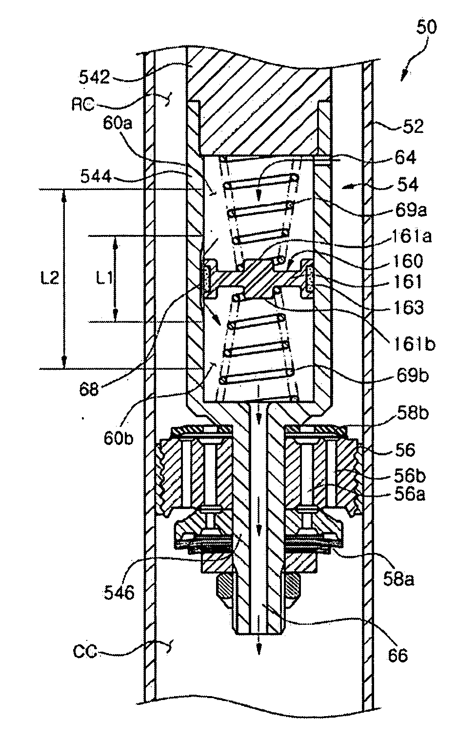
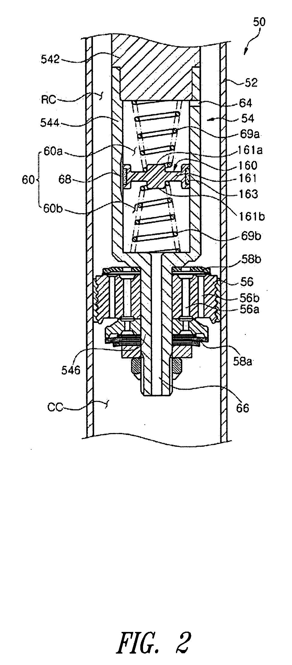
[0049]In this manner, the shock absorber 50 generates a very low damping force while the operating fluid is bypassed from one chamber to the other chamber through the groove 68.

[0050]Referring to FIG. 4 showing operation of the shock absorber 50 to generate a low damping force, a relatively large displacement of the piston rod 54 causes the floating piston 160 to move between an outer region of the section L1 having the bypass passage defined by the groove 68 and the maximum range of motion L2 of the floating piston 160.

[0051]In this case, a resilient force is generated by the upper and lower springs 69a and 69b to rapidly move the floating piston 160.

[0052]That is, when the piston rod 54 of the shock absorber 50 is relatively largely displaced, the floating piston 160 is moved between L1 and L2. Further, in the tensile stroke of the piston rod 54, that is, when the piston rod 54 is raised, the floating piston 160 is rapidly moved downward by a restoration force of the upper spring...

second embodiment

[0071]In this manner, when the piston rod 54 is minutely moved, the shock absorber 51 generates a very low damping force while the operating fluid is moved within the hollow chamber 60 by deformation of the flexible moving plate 264.

[0072]Referring to FIG. 8 showing operation of the shock absorber 51 to generate a low damping force, a relatively large displacement of the piston rod 54 causes the floating piston 260 to move between an outer region of the section L1 and the maximum range L2 of motion of the floating piston 260 while the flexible moving plate 264 is deformed at the same time.

[0073]Further, in the tensile stroke of the piston rod 54, that is, when the piston rod 54 is raised, the floating piston 260 is lowered while the flexible moving plate 264 is deformed downward at the same time. Accordingly, the operating fluid in the tensile chamber RC is supplied to the upper chamber 60a, while the operating fluid in the lower chamber 60b is discharged to the compression chamber...


PUM


Abstract

Disclosed herein is a shock absorber for damping vibration transmitted to a vehicle according to a road state. The shock absorber includes a cylinder and a piston valve disposed within the cylinder and connected to a piston rod to divide the cylinder into a first chamber and a second chamber. The piston rod includes a hollow chamber formed within the piston rod, first and second orifices formed in upper and lower ends of the hollow chamber and connected to the first and second chambers, respectively, a floating piston disposed within the hollow chamber to move up and down and to divide the hollow chamber into upper and lower chambers, and a moving mechanism formed in the hollow chamber to move an operating fluid to upper and lower portions of the floating piston. The shock absorber can change a damping force according to a displacement of the piston rod, thereby improving driving comfort and stability of the vehicle.

Description

BACKGROUND OF THE INVENTION[0001]1. Technical Field[0002]The present disclosure generally relates to shock absorbers for damping vibration transmitted to a vehicle according to a road state and, more particularly, to a shock absorber capable of changing a damping force according to a displacement of a piston rod.[0003]2. Description of the Related Art[0004]Generally, a vehicle is provided with a suspension system for enhancing driving comfort by buffering impact or vibration transmitted to an axle from a road during driving. One component constituting the suspension system is a shock absorber. The shock absorber is disposed between the axle and a vehicle body. The shock absorber includes a cylinder and a piston rod reciprocating within the cylinder. The cylinder is filled with an operating fluid, such as gas or oil, such that the operating fluid is moved by a piston valve secured to one end of the piston rod to generate a damping force.[0005]A conventional shock absorber has a restr...

Claims


Application Information

Patent Timeline
Patent Type & Authority Applications(United States)
IPC IPC(8): F16F9/34
CPCF16F9/5126
Inventor KIM, NAM HO
Owner HL MANDO CORP
Why Eureka
Try Eureka