Load tap changer

a technology of load tap and switch, which is applied in the direction of automatic control, process and machine control, instruments, etc., can solve the problems of arc between contacts, add to the cost and weight of the total assembly, and add to the total internal loss

Inactive Publication Date: 2009-06-11
PENNSYLVANIA TRANSFORMER TECH
View PDF16 Cites 23 Cited by
  • Summary
  • Abstract
  • Description
  • Claims
  • Application Information

AI Technical Summary

Benefits of technology

[0019]In an alternate embodiment, a method of delivering power to a load includes operating a circuit having a mechanical switch in a first conducting position and a first moving contact in electrical connection with a first tap of a transformer, so that the mechanical switch and first moving contact create a first circuit between a source and a load. A second contact is moved to create an electrical connection between the second contact and a second tap of the transformer. The mechanical switch is moved away from the first conducting position and toward a second conducting position. A gate trigger circuit triggers a first semiconductor device to complete a circuit between the source and the load through the first semiconductor device. A second gate trigger circuit triggers a second semiconductor device to complete a circuit between the source and the load through the second semiconductor device. The first gate trigger circuit then removes the trigger from the first semiconductor device, which subsequently stops conducting. When the mechanical switch reaches the second conducting position, a second circuit is created between the source and the load by shunting the second semiconductor device and passing current through the mechanical switch. The method may maintain a level of current delivered to the load at a substantially constant level as the mechanical switch moves from the first conducting position to the second conducting position. The event of the first semiconductor device turning off may be responsive to a current zero through the mechanical switch. Triggering and conduction of the second semiconductor device may be responsive to detection of voltage across either the first semiconductor device or the second semiconductor device in excess of a peak voltage of a winding of the transformer.

Problems solved by technology

The interruption of a high load current can lead to an arc between the contacts.
It significantly adds to the cost and weight of the total assembly.
It typically will also add to total internal losses, the resulting heat having to be dissipated with additional tank cooling provisions.
Thus, it often adds an unnecessary expense.
In addition, reliability issues can be extensive since the thyristors must be continuously active.
A problem with hybrid designs is that they involve the use of a means (usually a power resistor) to limit the magnitude of a current that may circulate in the electronic circuit during the tap change.
Prior hybrid systems also require multiple power switches, further adding to the cost of the circuit.

Method used


Image

  • Load tap changer
  • Load tap changer
  • Load tap changer

Examples


Embodiment Construction

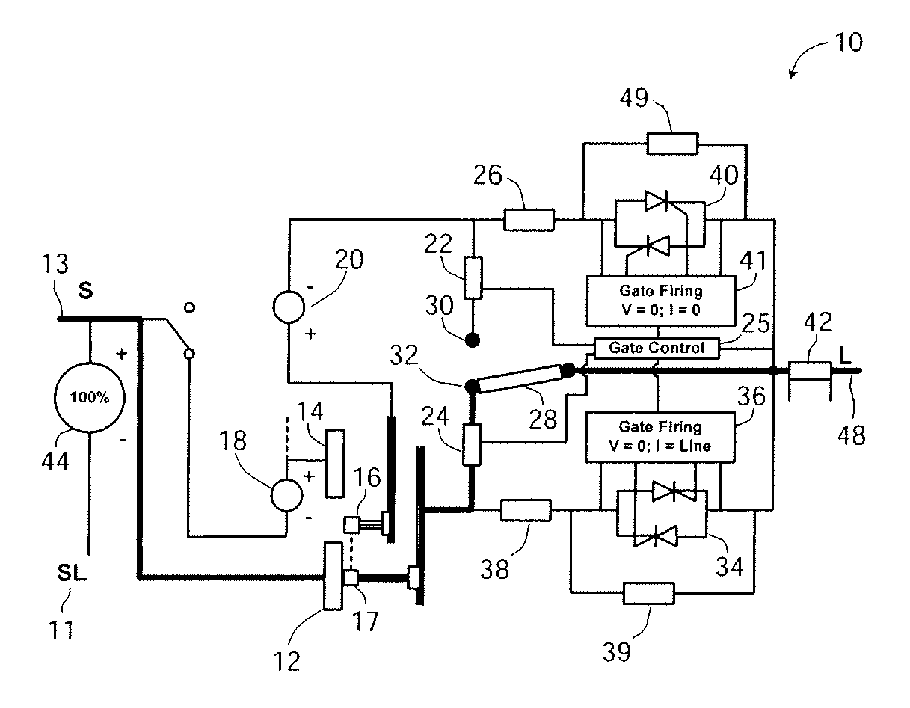
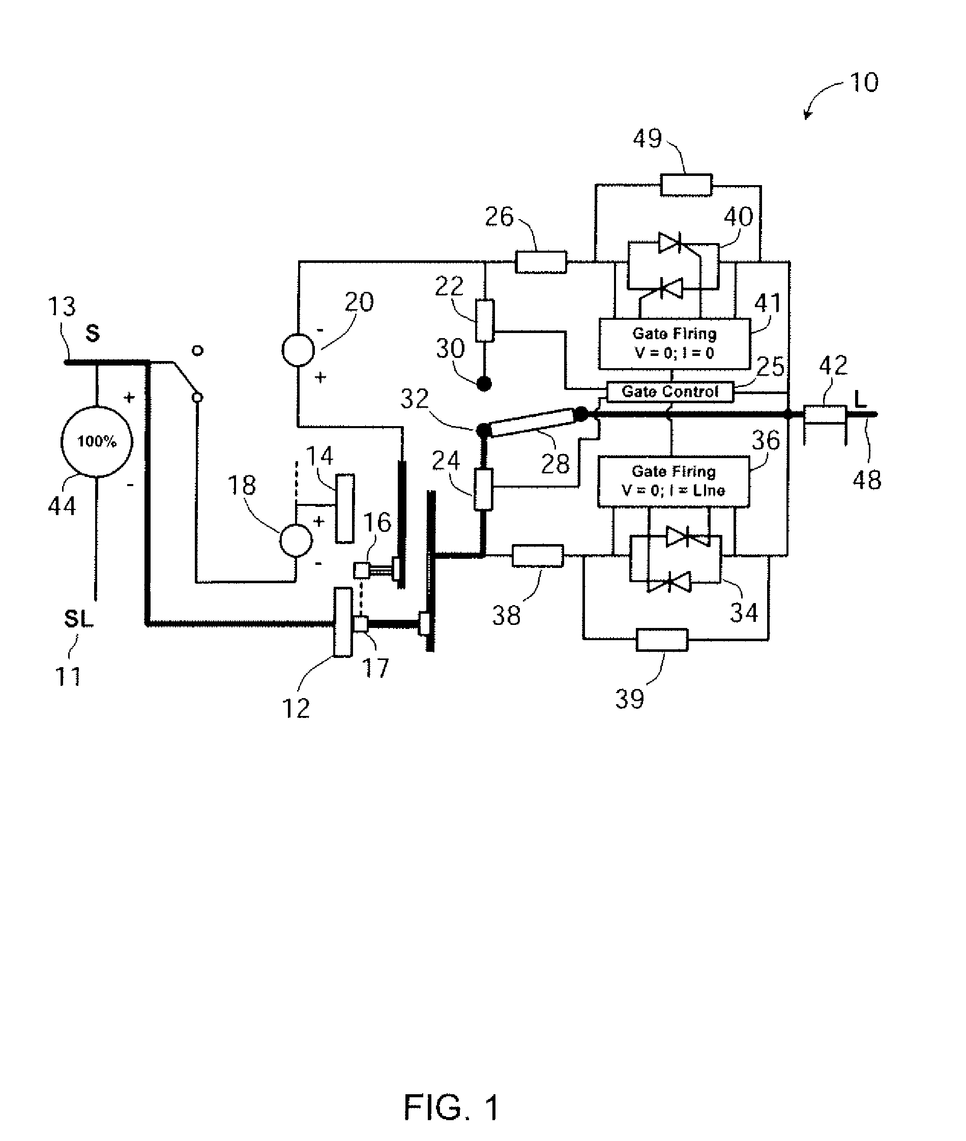
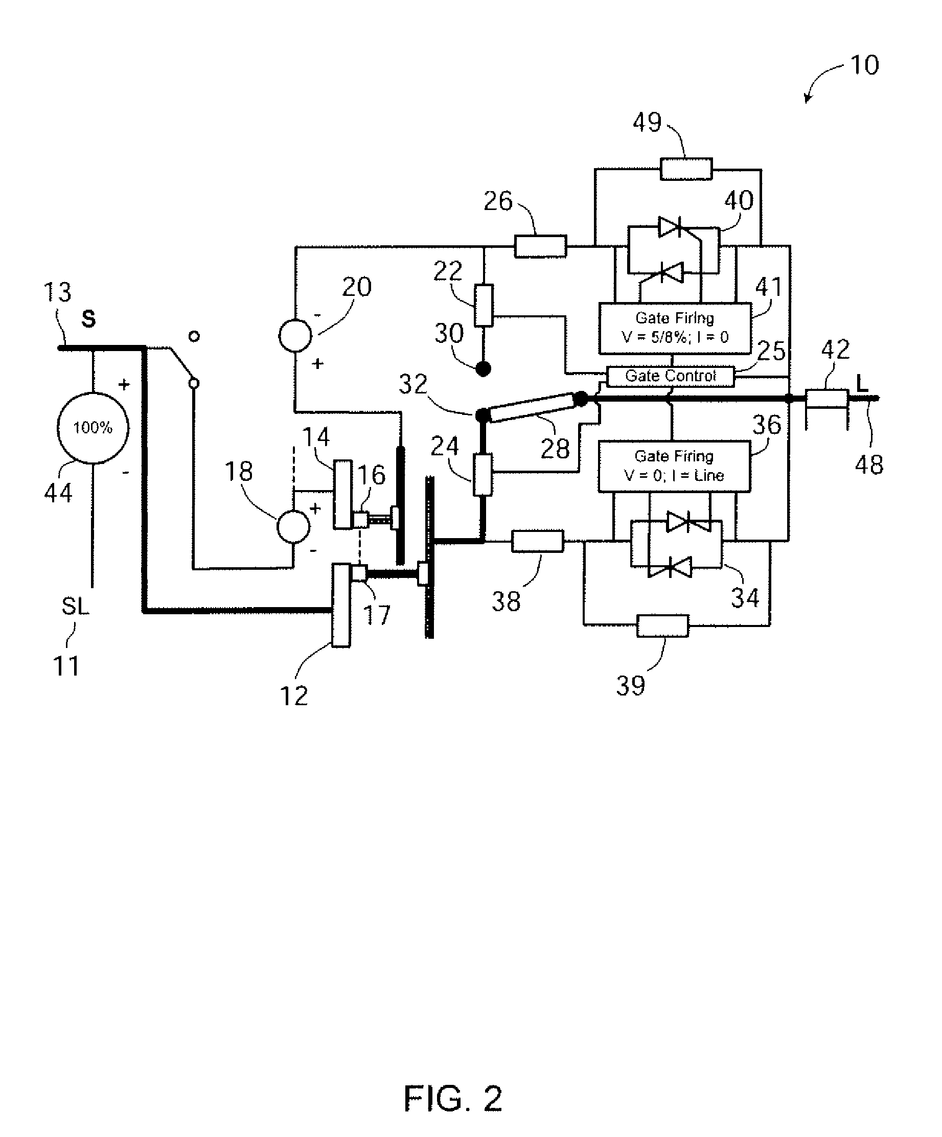
[0028]Before the present methods, systems and materials are described, it is to be understood that this disclosure is not limited to the particular methodologies, systems and materials described, as these may vary. It is also to be understood that while all circuit descriptions reveal a single-phase implementation, the methods and systems described herein also include multi-phase applications. It is also to be understood that the terminology used in the description is for the purpose of describing the particular versions or embodiments only, and is not intended to limit the scope. For example, as used herein and in the appended claims, the singular forms “a,”“an,” and “the” include plural references unless the context clearly dictates otherwise. In addition, the word “comprising” as used herein is intended to mean “including but not limited to.” Unless defined otherwise, all technical and scientific terms used herein have the same meanings as commonly understood by one of ordinary s...


PUM


Abstract

A load tap changer includes a single mechanical switch that is movable to create, in a first position, a first conducting path between a first transformer tap and a load. When the switch is in a second position, the switch creates a second conducting path between a second transformer tap and the load. A first thyristor pair or other device creates a first alternate conducting path between the first transformer tap and the load when the switch is disengaged from the first position. A second thyristor pair or other device creates a second alternate conducting path between the second transformer tap and the load when the mechanical switch is disengaged from the second position. Each thyristor pair may be selectively triggered to provide a conducting path when voltage across either thyristor pair exceeds a predetermined level. A gate trigger circuit may be included for each thyristor pair, and a gate control circuit may control each of the gate trigger circuits.

Description

CROSS-REFERENCE TO RELATED APPLICATIONS[0001]Not applicable.STATEMENT REGARDING FEDERALLY SPONSORED RESEARCH[0002]Not applicable.NAMES OF PARTIES TO A JOINT RESEARCH AGREEMENT[0003]Not applicable.SEQUENCE LISTING[0004]Not applicable.BACKGROUND[0005]1. Technical Field[0006]The disclosed embodiments generally relate to the field of voltage regulating or control systems. More particularly, the disclosed embodiments relate to an improved tap changing method and system for power delivery.[0007]2. Description of the Related Art[0008]A tap changer is a device used to change the load voltage or phase angle of a power delivery system. Typically, the selection of a tap adjusts the number of turns used in one or more of a transformer's windings. Tap changers most commonly are used to permit the regulation of the output voltage of a transformer or step voltage regulator to a desired level.[0009]Tap changing may occur either while the transformer is energized (i.e., under load) or while the tran...

Claims


Application Information

Patent Timeline
Patent Type & Authority Applications(United States)
IPC IPC(8): G05B24/02
CPCH01F29/04H01H9/542H01H9/0005
Inventor STICH, FREDERICK A.HARLOW, JAMES H.GRIESACKER, WILLIAM F.
Owner PENNSYLVANIA TRANSFORMER TECH
Why Eureka
Try Eureka