Fan and rotor of motor thereof

a technology of rotor and fan, which is applied in the direction of magnetic circuit rotating parts, piston pumps, magnetic circuit shapes/forms/construction, etc., can solve the problems of high cost of rotor b>10/b>, high material and processing costs of copper, and complicated manufacturing processes, so as to reduce the manufacturing cost of the fan and increase the connection strength. , the effect of simplifying the manufacturing process

Inactive Publication Date: 2009-06-11
DELTA ELECTRONICS INC
View PDF15 Cites 23 Cited by
  • Summary
  • Abstract
  • Description
  • Claims
  • Application Information

AI Technical Summary

Benefits of technology

[0008]In view of the foregoing, the present invention provides a fan and a rotor of a motor thereof, wherein the central portion of a top wall of a magnetically conductive shell has an extending portion disposed adjacent to a groove of a shaft, and an connecting element is provided to connect the magnetically conductive shell and the shaft, so that the connecting strength between the magnetically conductive shell and the shaft can be increased, the manufacturing process can be simplified, and the manufacturing cost can be decreased.
[0011]As mentioned above, the fan and the rotor of its motor according to the present invention have the following features. The central portion of the top wall of the magnetically conductive shell has at least one extending portion disposed adjacent to the groove, and the extending portion is radially projected onto the groove. The relative positions between the connecting element, the extending portion and the groove could be varied depending on actual needs. In comparison with the prior art, the connecting element, the magnetically conductive shell and the shaft of the present invention are connected so as to increase the connecting strength between the magnetically conductive shell and the shaft. In addition, the connecting element, the hub and the blades of the present invention can be formed by molding, so that the manufacturing process is simplified and the manufacturing cost of the fan is decreased.

Problems solved by technology

In addition, the copper sleeve 13 is heavy, and the material and processing costs of the copper sleeve 13 are expensive, so that cost of the rotor 10 is high and its manufacturing process is complicated.

Method used


Image

  • Fan and rotor of motor thereof
  • Fan and rotor of motor thereof
  • Fan and rotor of motor thereof

Examples


first embodiment

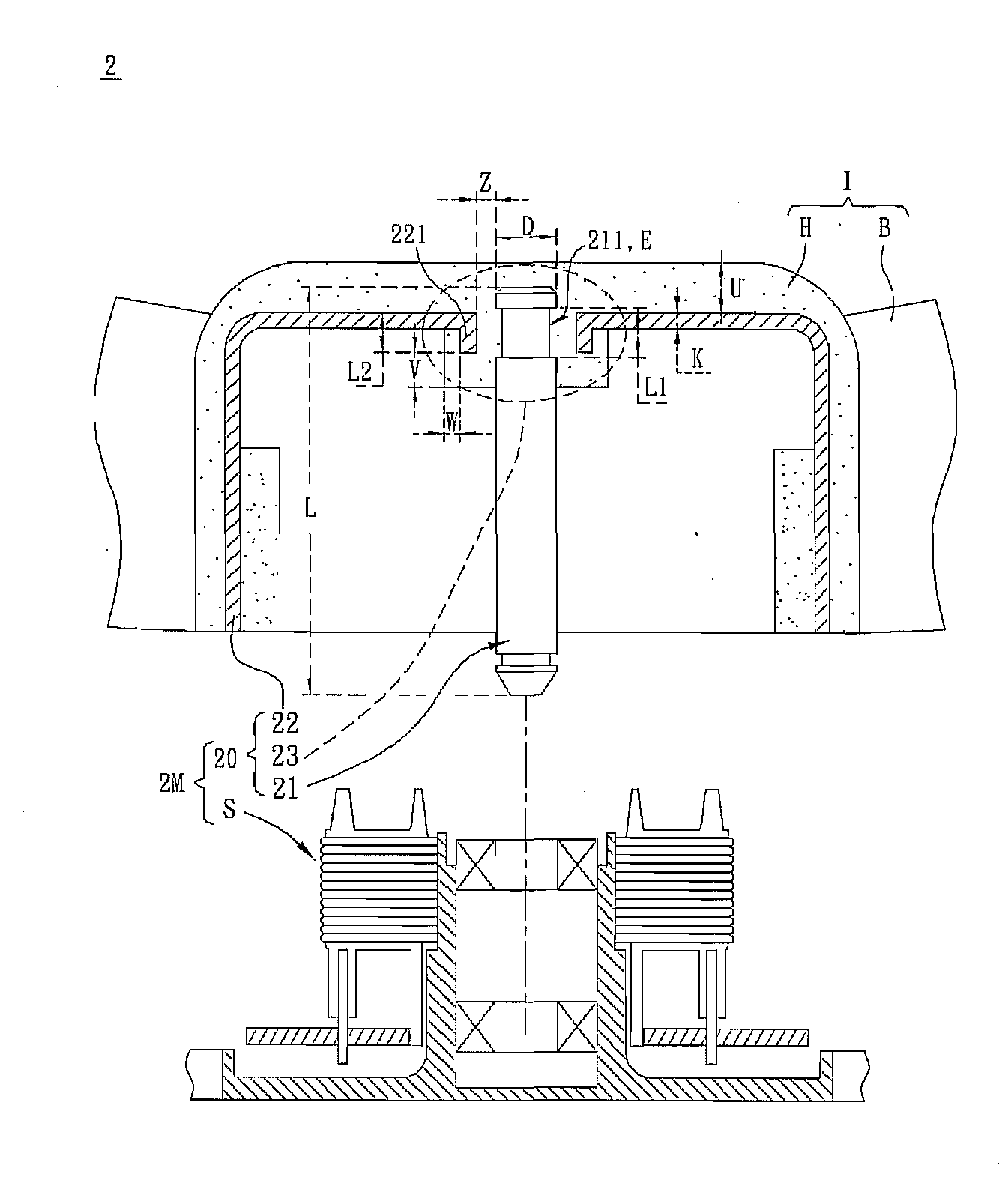
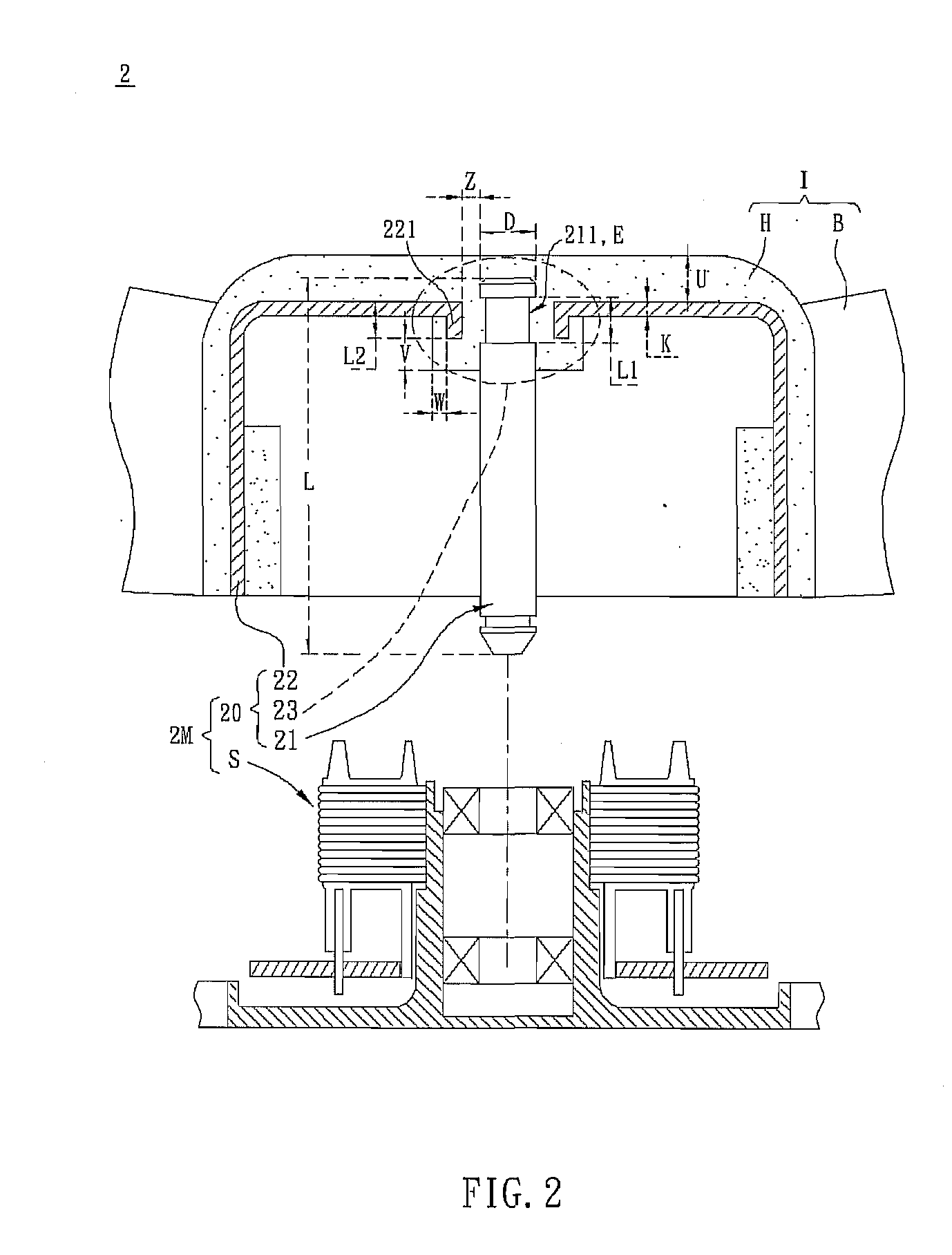
[0021]Referring to FIG. 2, a fan 2 according to the present invention includes an impeller I and a motor 2M. In this embodiment, the fan 2 is an axial fan having an outer-rotor motor. The impeller I has a hub H and a plurality of blades B disposed around the hub H. The motor 2M drives the impeller I to rotate. The motor 2M has a rotor 20 and a stator S disposed corresponding to the rotor 20. The rotor 20 includes a shaft 21, a magnetically conductive shell 22 and a connecting element 23. One end E of the shaft 21 has a groove 211. The central portion of a top wall of the magnetically conductive shell 22 has at least one extending portion 221 disposed adjacent to the groove 211, and at least one part of the extending portion 221 is radially projected onto the groove 211. In other words, at least one part of the extending portion 221 is disposed corresponding to the groove 211.

[0022]In this embedment, the extending portion 221 is extended in parallel to the groove 211 and then extende...

second embodiment

[0026]Referring to FIG. 5, a fan 5 according to the present invention includes an impeller I and a motor 5M. The motor 5M has a rotor 50 and a stator S disposed corresponding to the rotor 50. The rotor 50 includes a shaft 21, a magnetically conductive shell 52, and a connecting element 53. The main structures and functions of the impeller I and the motor 5M are the same as that of the impeller I and the motor 2M of the previous embodiment, so the detailed descriptions are omitted for concise purpose.

[0027]The difference between the rotor 20 and the rotor 50 is that the extending portion 521 of the rotor 50 is extended obliquely downwards from the central portion of the top wall of the magnetically conductive shell 52 and embedded in the connecting element 53. An angle θ is formed between the extending direction of the extending portion 521 and the axial direction of the shaft 21. In this case, the angle θ is smaller than 90 degrees. The dimensions of the extending portion 521 of the...

third embodiment

[0029]Referring to FIG. 7, a fan 7 according to the present invention includes an impeller I and a motor 7M. The motor 7M has a rotor 70 and a stator S disposed corresponding to the rotor 70. The rotor 70 includes a shaft 21, a magnetically conductive shell 72, and a connecting element 73. The main structures and functions of the impeller I and the motor 7M are the same as that of the impeller I and the motor 5M of the previous embodiment, so the detailed descriptions are omitted for concise purpose.

[0030]The difference between the rotor 50 and the rotor 70 is that the extending portion 721 of the rotor 70 is extended obliquely downwards from the central portion of the top wall of the magnetically conductive shell 72, and then extended upwards with parallel to the groove 211 so as to form a turn. Herein, the extending portion 721 is embedded in the connecting element 73. The dimensions of the extending portion 721 of the magnetically conductive shell 72, the length L1 of the groove ...


PUM


Abstract

A rotor of a motor includes a shaft, a magnetically conductive shell and a connecting element. The shaft has a groove formed at one end of the shaft. The central portion of a top wall of the magnetically conductive shell has at least one extending portion disposed adjacent to the groove, and at least one part of the extending portion is radially projected onto the groove. The connecting element connects the end of the shaft and the extending portion of the magnetically conductive shell. A fan including above-mentioned rotor is also disclosed.

Description

CROSS REFERENCE TO RELATED APPLICATIONS[0001]This Non-provisional application claims priority under 35 U.S.C. §119(a) on Patent Application No(s). 096220687, filed in Taiwan, Republic of China on Dec. 6, 2007, the entire contents of which are hereby incorporated by reference.BACKGROUND OF THE INVENTION[0002]1. Field of Invention[0003]The present invention relates to a fan and a motor thereof, and more particular to a fan and a rotor of a motor thereof.[0004]2. Related Art[0005]Generally speaking, the rotor of a conventional fan is connected to the magnetically conductive shell through a shaft. The shaft passes through the stator of the motor, and the impeller covers the magnetically conductive shell. After accomplishing the assembling, the motor can drive the impeller to rotate so as to operate the fan.[0006]Referring to FIG. 1, a conventional rotor 10 includes a shaft 11, an iron housing 12 and an impeller I. The impeller I has a hub H and a plurality of blades B connected to the h...

Claims


Application Information

Patent Timeline
Patent Type & Authority Applications(United States)
IPC IPC(8): F16C35/00F04D25/08
CPCH02K1/30H02K1/2786F04D25/0613F04D29/023F04D29/329H02K1/2787
Inventor KUO, YI-CHENSHAO, CHIA-CHIYAN, CHENG-WEICHUANG, TE-TSAI
Owner DELTA ELECTRONICS INC
Why Eureka
Try Eureka