Image forming apparatus

Inactive Publication Date: 2009-06-11
KYOCERA DOCUMENT SOLUTIONS INC
View PDF4 Cites 20 Cited by
  • Summary
  • Abstract
  • Description
  • Claims
  • Application Information

AI Technical Summary

Benefits of technology

[0018]According to the present invention, in the image forming apparatus structured as described above, it is preferable that the control section make the motor stop rotating in a case where the current detecting section has not detected an overcurrent flowing through the motor when a time twice as long as the set time has elapsed from a start of driving of the motor. With this structure, since the control section makes the motor stop being driven, it is possible to prevent the motor from being overheated in the case where no overcurrent has been detected flowing through the motor when a time twice as long as the time has elapsed from a start of the driving of the motor, the case suggesting that some trouble has occurred in the current detecting section or that the load is large, where there is a possibility that an overcurrent will continue flowing through the motor. However, in this case, the motor is made to stop being driven, and thereby, it is prevented from being overheated.
[0019]According to the present invention, it is preferable that the image forming apparatus structured as described above include a display section for displaying a state of the apparatus. Here, the display section displays an alert message in a case where the current detecting section detects an overcurrent flowing through the motor in the erroneous detection checking operation. With this structure, in the case where the cleaning member cannot perform proper cleaning operation, an alert message displayed on the display section enables the user to be informed that image formation will be negatively affected. In a case where an overcurrent flows through the motor more than necessary, an alert message displayed on the display section enables the user to be informed that the cleaning mechanism needs to be checked.
[0020]According to the present invention, it is preferable that the image forming apparatus structured as described above include for forming a toner image: a photoconductive drum functioning as an image carrier; and an exposure device that performs scanning and exposure of the photoconductive drum by use of laser light according to image data of an image to be formed. Here, a plate-shaped member that transmits light is attached to the exposure device at a portion thereof from which laser light is emitted toward the photoconductive drum, that the plate-shaped member be in contact with the cleaning member of the movable body, and that the plate-shaped member be the target to be cleaned. With this structure, since cleaning of the plate-shaped member of the exposure device can be securely performed without being negatively affect

Problems solved by technology

With this structure, in the case where an overcurrent is detected flowing through the motor both when the motor is rotating forward and when it is rotating backward, which sugge

Method used


Image

  • Image forming apparatus
  • Image forming apparatus
  • Image forming apparatus

Examples


Example

[0032]Hereinafter, a description will be given of an embodiment of the present invention with reference to the drawings. It should be understood that factors such as structures and arrangements described in this embodiment are not meant to limit the scope of the present invention, but are merely examples used for describing the present invention.

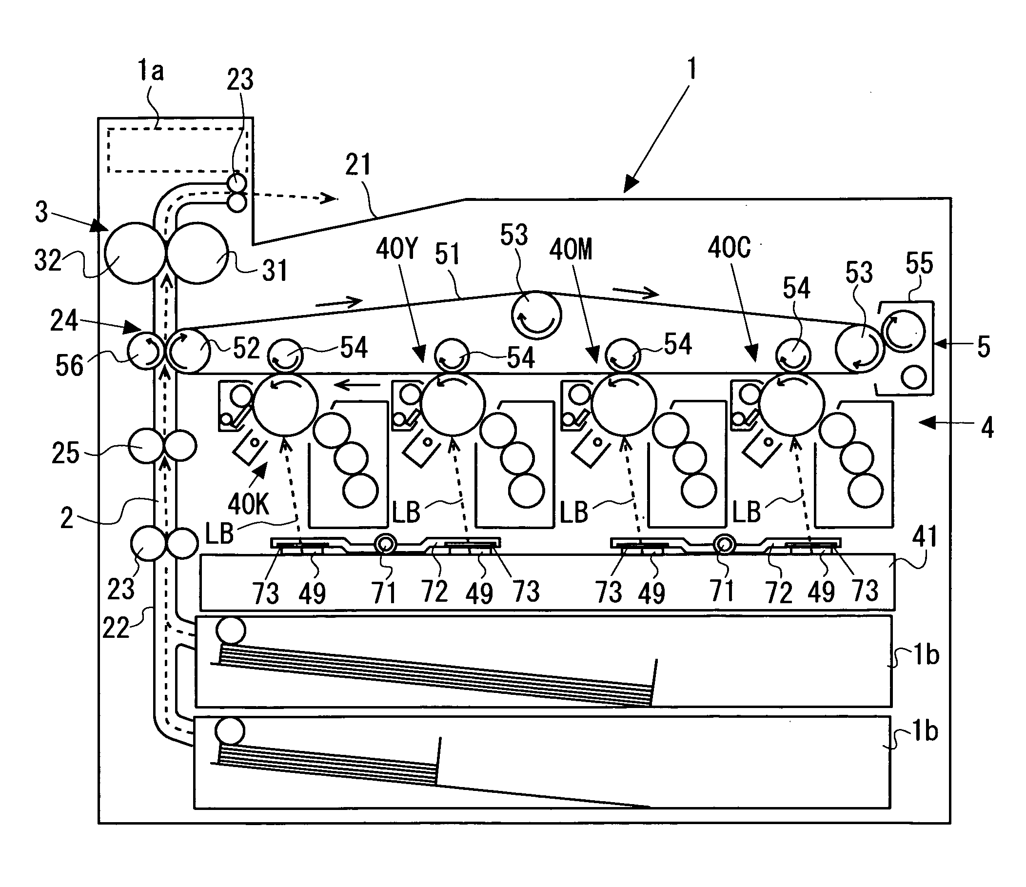
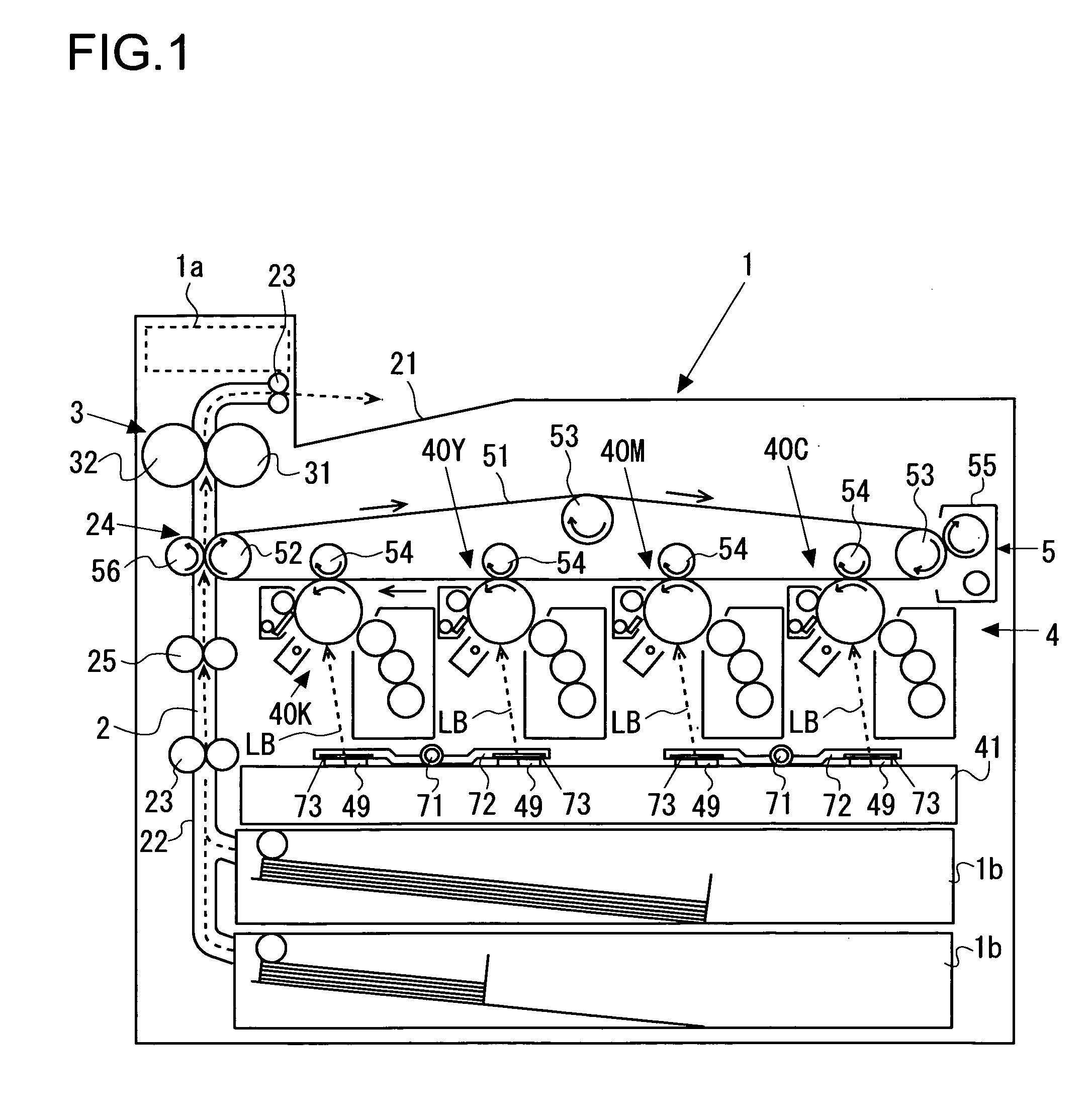
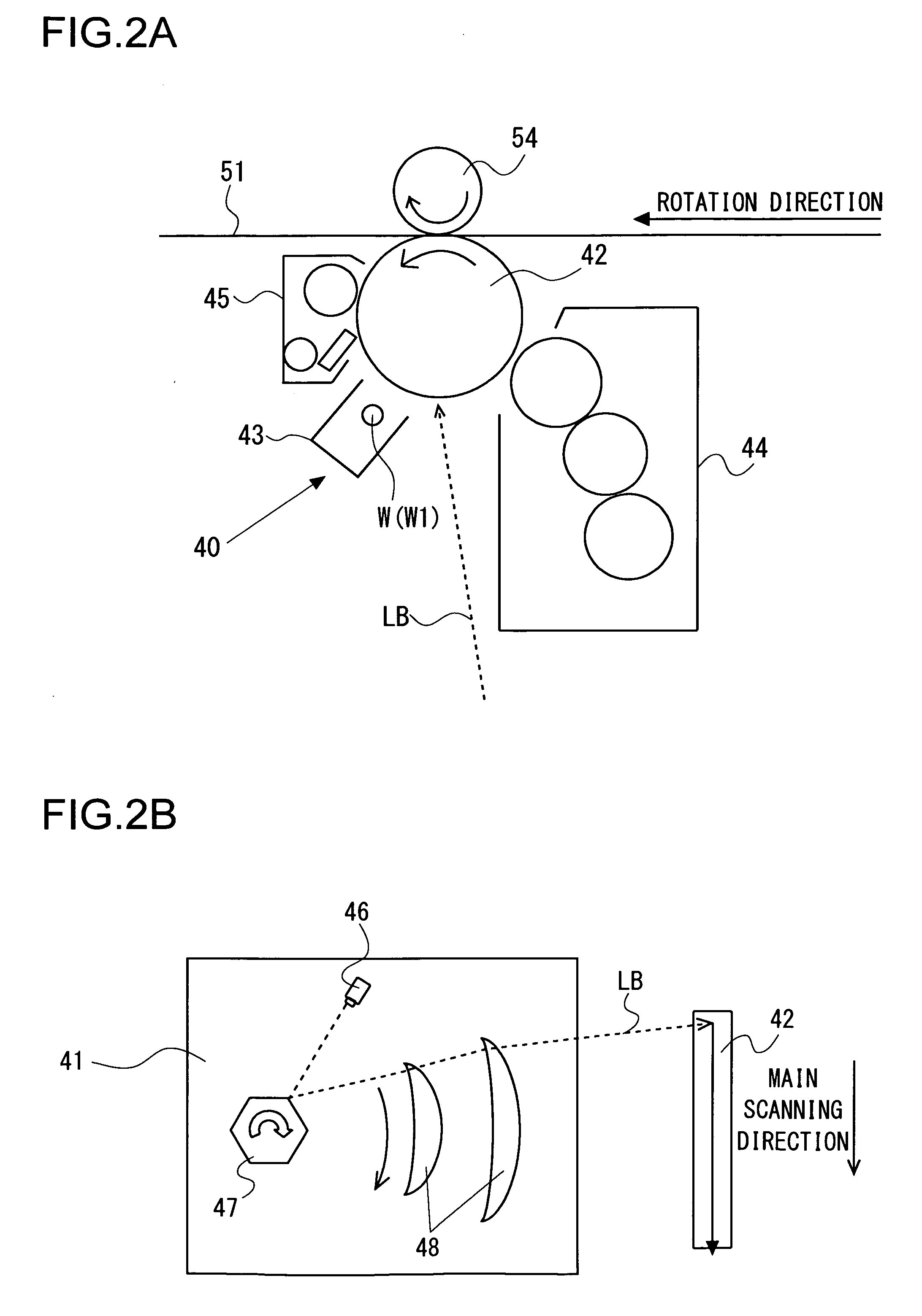
[0033]First, with reference to FIGS. 1, 2A, and 2B, a description will be given of outline of the structure and operation of a printer 1 (which corresponds to an image forming apparatus) of this embodiment. FIG. 1 is a front sectional view schematically showing the structure of the printer 1 embodying the present invention. FIG. 2A is an enlarged sectional view schematically showing an image forming unit embodying the present invention, and FIG. 2B is a diagram schematically showing a laser unit embodying the present invention.

[0034]As shown in FIG. 1, the printer 1, which has a control panel 1a (indicated by a broken line in FIG. 1, corresp...


PUM


Abstract

An image forming apparatus includes: a rotation shaft (71);a movable body (72) that is attached to the rotation shaft (71), that is provided with a cleaning member (73), and that moves with rotation of the rotation shaft (71); a motor M for rotating the rotation shaft (71); a control section (8) for controlling rotation of the motor M; a current detecting section (77) for detecting a current flowing through the motor M; and a time counting section for counting time. Here, the control section is provided with: an overcurrent detection checking function; a time counting function; a predetermined position attainment checking function; a reciprocation control function; an erroneous detection checking function for performing erroneous detection checking operation in which an overcurrent detected while the movable body is moving forward in the reciprocation thereof is checked while the movable body is moving backward in the reciprocation thereof; and a repeating function for performing the erroneous detection checking operation once or a plurality of times in a repeating fashion.

Description

[0001]This application is based on Japanese Patent Application No. 2007-318260 filed on Dec. 10, 2007, the contents of which are hereby incorporated by reference.BACKGROUND OF THE INVENTION[0002]1. Field of the Invention[0003]The present invention relates to an image forming apparatus such as a printer, a copier, a facsimile machine, and a multifunctional system that performs cleaning of a member by using a motor for rotating a rotation shaft to move a movable body.[0004]2. Description of Related Art[0005]Image forming apparatuses are sometimes provided with a mechanism that uses a motor or the like to automatically remove stain caused by dust of toner, external additives of toner (e.g., silica), and the like. For example, in an image forming apparatus in which a photoconductive drum is charged by corona discharge from a wire, electrostatic force generated by a voltage applied to the wire may sometimes cause a substance such as dust of silica to adhere to the wire, and this substanc...

Claims


Application Information

Patent Timeline
IPC IPC(8): G03G21/00
CPCG03G15/0258G03G21/00G03G2215/0404G03G15/04072G03G2221/1636G03G2221/1693G03G2221/1618
Inventor TAJIMA, SHINICHI
Owner KYOCERA DOCUMENT SOLUTIONS INC
Why Eureka
Try Eureka