
Device for housing electrochemical cells

a technology for electrochemical cells and devices, applied in cell components, electrochemical generators, electrical apparatus, etc., can solve the problems of affecting the service life of the battery, so as to promote easy serviceability, uniform cell cooling, and convenient stacking and removal of individual modules

Active Publication Date: 2009-06-11
BATTERY PATENT TRUST
View PDF14 Cites 43 Cited by
  • Summary
  • Abstract
  • Description
  • Claims
  • Application Information

AI Technical Summary

Benefits of technology

[0007]Disclosed herein is a battery module housing having a first semi-enclosure and a second semi-enclosure, wherein the first and second semi-enclosure are aligned to form compartments there between. Each compartment is designed to accommodate at least one electrochemical cell, such as a cylindrical battery or a prismatic battery. Preferably, the shape of each compartment is designed to correspond with the exterior form of the electrochemical cell disposed within the compartment to provide intimate contact between the electrochemical cell and the housing.
[0010]The battery modules may be interlocked in a staggered formation to minimize space. The exterior portion of the exterior wall of each semi-enclosure further comprises a series of slots and slats which secure a plurality of module housings in place with respect to one another. This interlocking of module housings inhibits movement with respect to one another and provides improved packing density. Preferably, the module housings are aligned in a staggered formation to provide maximum packing density.
[0012]In another embodiment, more than one compartment may be set between the end walls by incorporating at least one stacking segment having a dual sided segment and semi-enclosure wall. The semi-enclosure wall is secured to an internal side of the dual sided segment to form at least one flow channel between the semi-enclosure wall and the internal side. At least one flow support may be set between the semi enclosure and the internal side. The flow support allows the coolant to be evenly distributed into intimate contact with the semi enclosure and the internal side and draw heat away from cells packed on either side of the stacking segment. Further, the flow support provides added structural support to the segment to withstand expansion from electrochemical cells as same charge and discharge. A top portion of the semi-enclosure may be sealed to the stacking segment manifold to allow the thermal management medium to flow through a desired pathway.
[0013]Embodiments of the invention provide uniform cell cooling by conforming the cell compartments of the housing to the shape of the cells. Embodiments of the invention provide dielectric isolation between the cell and the thermal management medium. Embodiments of the invention provide a modular design to promote easy serviceability by allowing convenient stacking and removal of individual modules. Embodiments of the invention provide a modular design which allows flexibility as far as battery pack size and energy needs of a given system. Embodiments of the invention allows for very compact packaging of cells as the modules are stacked next to one another. Embodiments of the invention provide alignment features to align and lock modules in relative position.

Problems solved by technology

Therefore, the batteries used in these applications may generate significant heat during operation.
The cells, with an increased electric capacity and sealed configuration, increase the amount of heat accumulated, with the result that heat dissipation out of the battery is retarded and the generated heat is accumulated within the battery.

Method used


Image

  • Device for housing electrochemical cells
  • Device for housing electrochemical cells
  • Device for housing electrochemical cells

Examples


Embodiment Construction

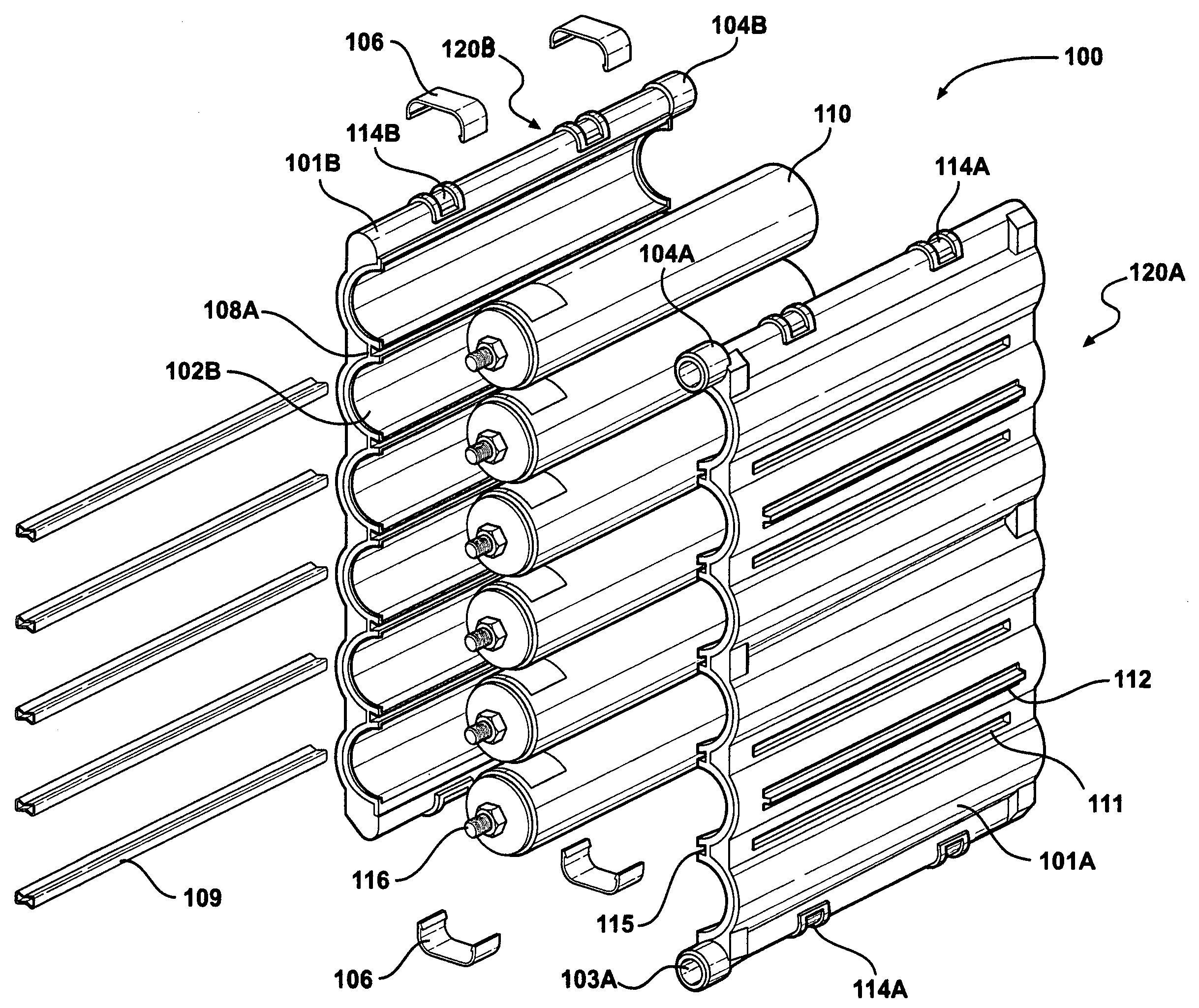
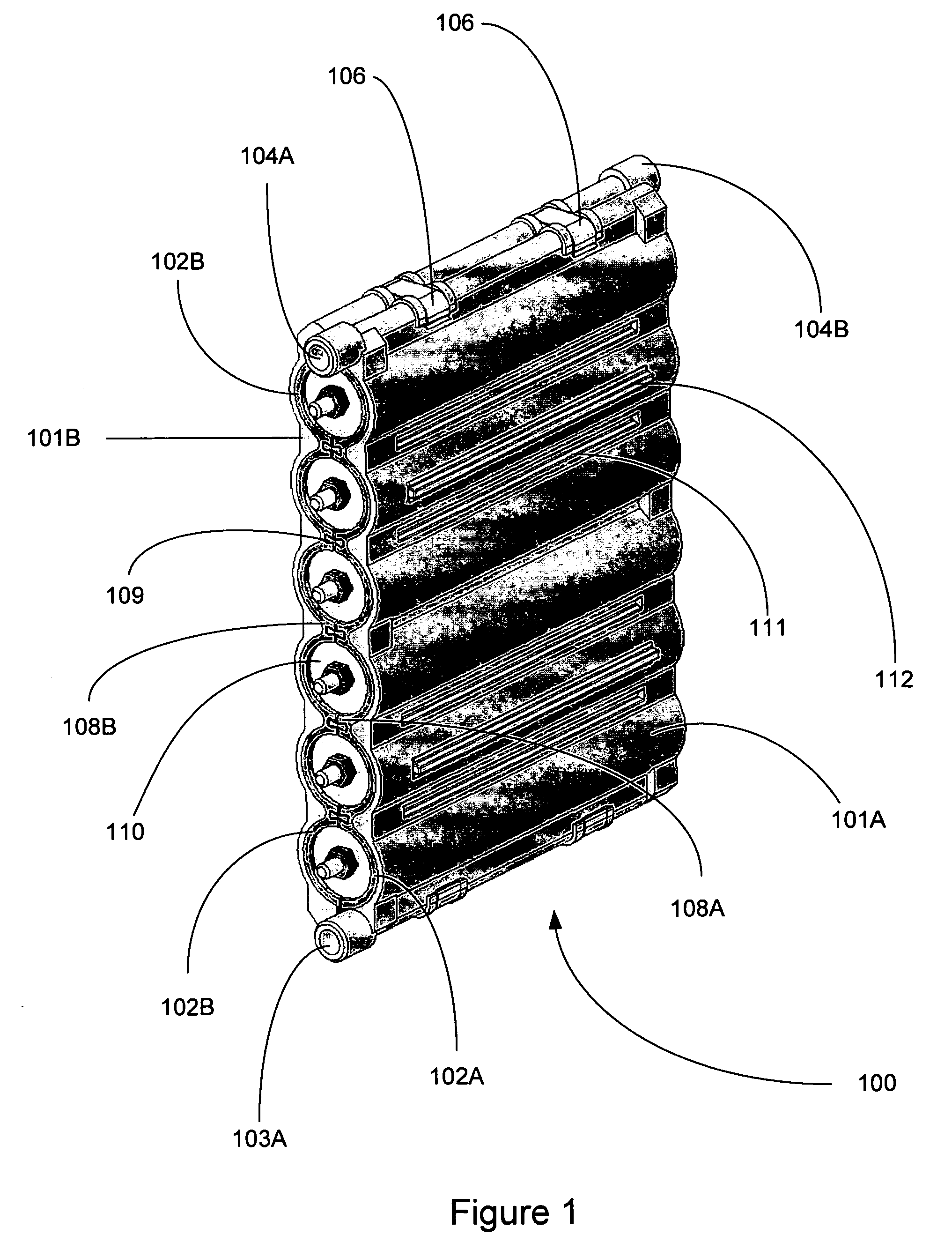
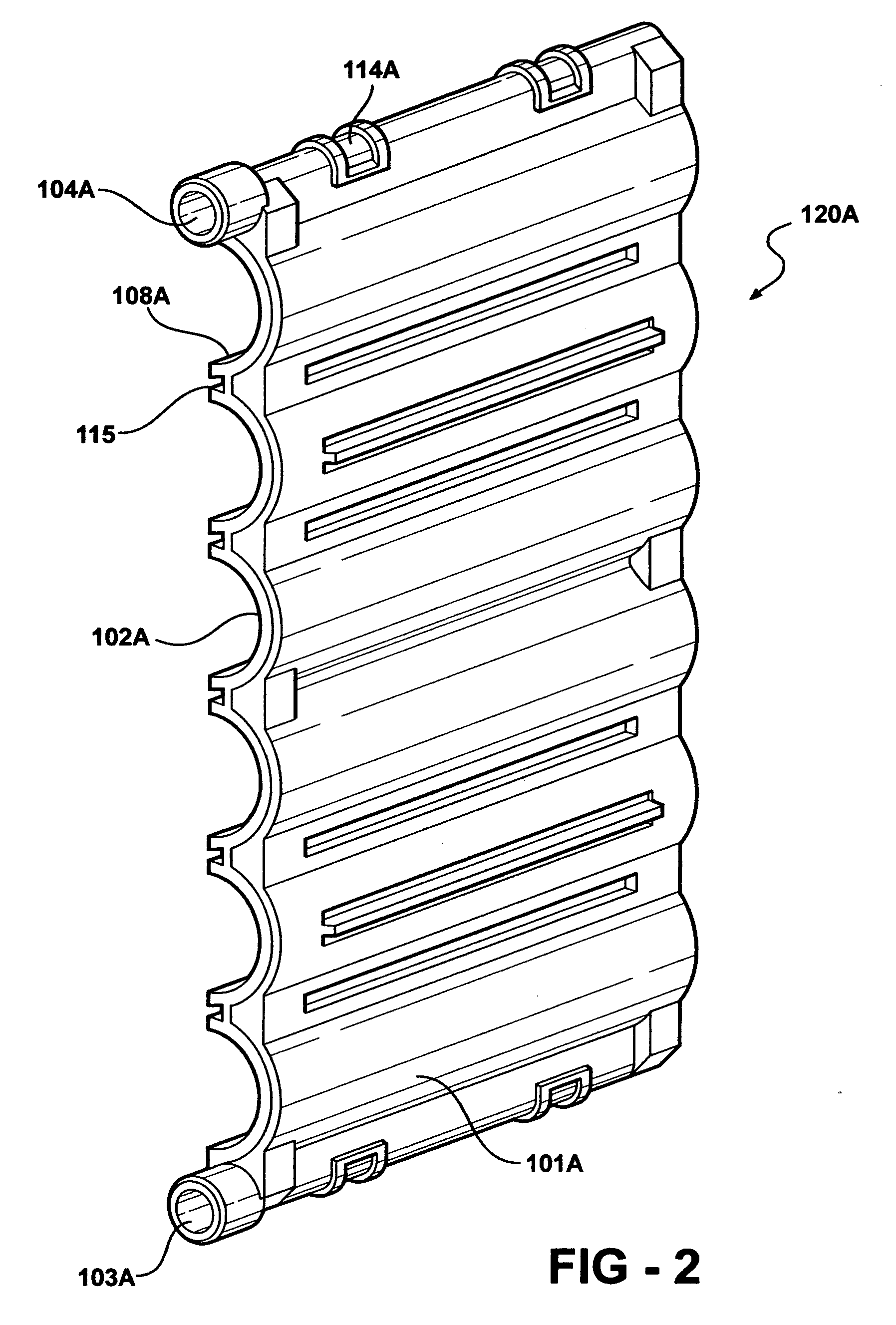
[0033]Referring to FIGS. 1 and 4, disclosed herein is a battery module housing 100 having a first semi-enclosure 120A and a second semi-enclosure 120B, wherein the first and second semi-enclosure are aligned to form compartments there between. Each compartment is designed to accommodate a single electrochemical cell 110, such as a cylindrical battery; however, the compartment may be designed accommodate other shapes, such as a prismatic battery. Preferably, the shape of each compartment is designed to correspond with the exterior form of the electrochemical cell 110 disposed within the compartment to provide intimate between the electrochemical cell 110 and the module housing 100.

[0034]Referring to FIGS. 1 through 4, each semi-enclosure 120A, 102B comprises an exterior wall 101A, 101B and an interior wall 102A, 102B. The exterior 101A, 101B and interior wall 102A, 102B align together to form a flow path between the walls through which coolant or any other thermal management medium m...


PUM

PropertyMeasurementUnit
stabilityaaaaaaaaaa
temperatureaaaaaaaaaa
packing densityaaaaaaaaaa

Abstract

Disclosed herein is a device for housing a plurality of electrochemical cells, wherein the housing provides stability, temperature control and maximum packing density. The battery module housing comprises a first semi-enclosure and a second semi-enclosure, wherein the first and second semi-enclosure are aligned to form compartments there between. Each compartment is designed to accommodate at least one electrochemical cell, such as a cylindrical battery or a prismatic battery. Each semi-enclosure comprises an interior wall and an exterior wall. The interior and exterior wall align together to form a flow path between the walls through which coolant or any other thermal management medium may flow. The coolant enters the semi-enclosure through a coolant inlet, flows between the interior and exterior walls; then flows out of the semi-enclosure through a coolant outlet.

Description

FIELD OF THE INVENTION[0001]The instant invention relates generally to improvements in rechargeable high performance batteries, modules and packs. Specifically, the invention relates to device for housing a plurality of cylindrical electrochemical cells, wherein the housing provides stability, temperature control and maximum packing density.BACKGROUND OF THE INVENTION[0002]Rechargeable batteries are used in a variety of industrial and commercial applications such as fork lifts, golf carts, uninterruptible power supplies, pure electric vehicles and hybrid electric vehicles. Vehicular applications include applications related to propulsion as well as applications related to starting, lighting and ignition.[0003]One aspect of battery operation that is particularly important for electric vehicle and hybrid vehicle applications is that of thermal management. In both electric and hybrid vehicle applications individual electrochemical cells are bundled together in close proximity. Many cel...

Claims


Application Information

Patent Timeline
Patent Type & Authority Applications(United States)
IPC IPC(8): H01M10/36H01M2/00H01M50/209H01M50/213H01M50/262H01M50/291
CPCH01M2/1077H01M2/1083H01M10/5004H01M10/5075H01M10/5055H01M10/5057H01M10/5063H01M10/5006H01M10/615H01M10/6556H01M10/6567H01M10/6555H01M10/6561H01M10/613Y02E60/10H01M50/209H01M50/213H01M50/291H01M50/262H01M10/655H01M10/656
Inventor MARCHIO, MICHAEL A.GOROG, JOZEF
Owner BATTERY PATENT TRUST
Learn More