
Silent chain

a technology of chain and silencer, applied in the direction of driving chains, chain elements, belts/chains/gearrings, etc., can solve the problems of premature wear of conventional chains, insufficient suppression of impact noise and impact force of conventional chains, etc., to reduce prolong the useful life of the chain, and absorb the effect of reducing the load on the joint row plates

Inactive Publication Date: 2009-06-11
TSUBAKIMOTO CHAIN CO
View PDF6 Cites 3 Cited by
  • Summary
  • Abstract
  • Description
  • Claims
  • Application Information

AI Technical Summary

Benefits of technology

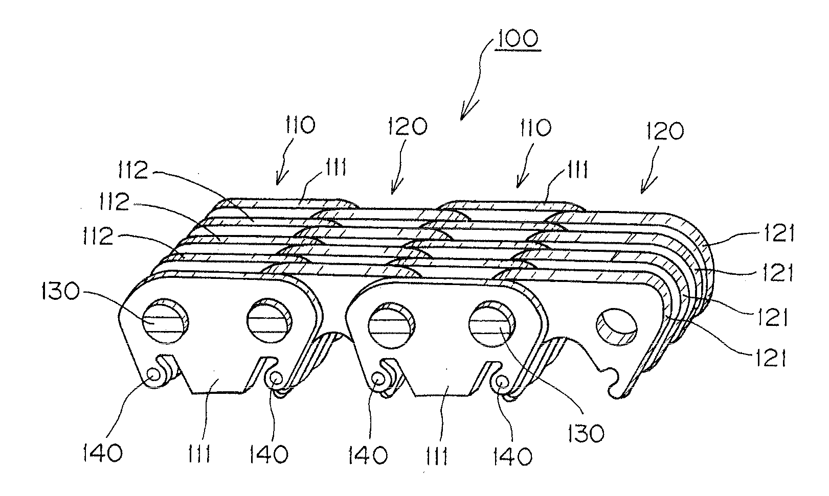
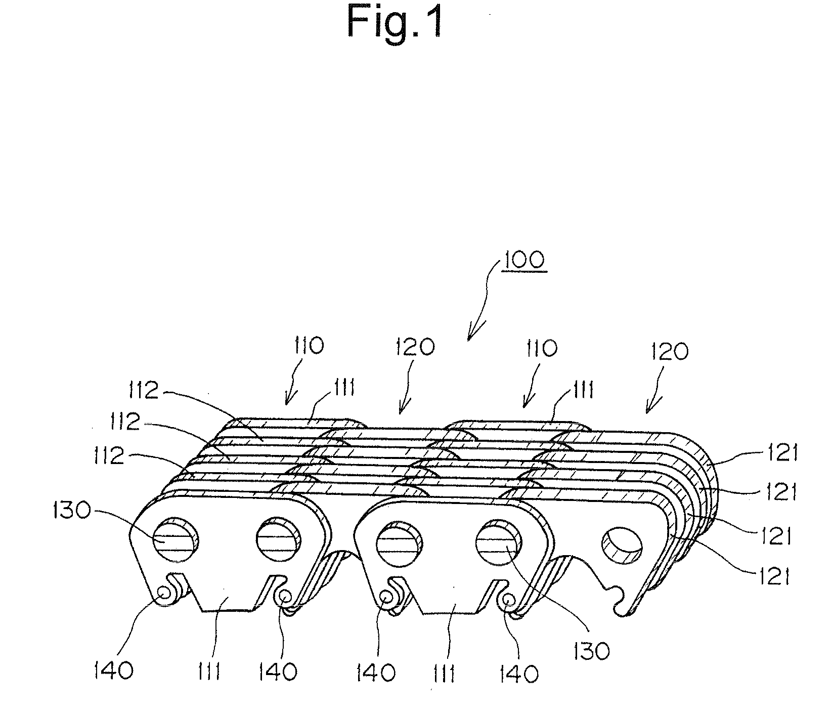
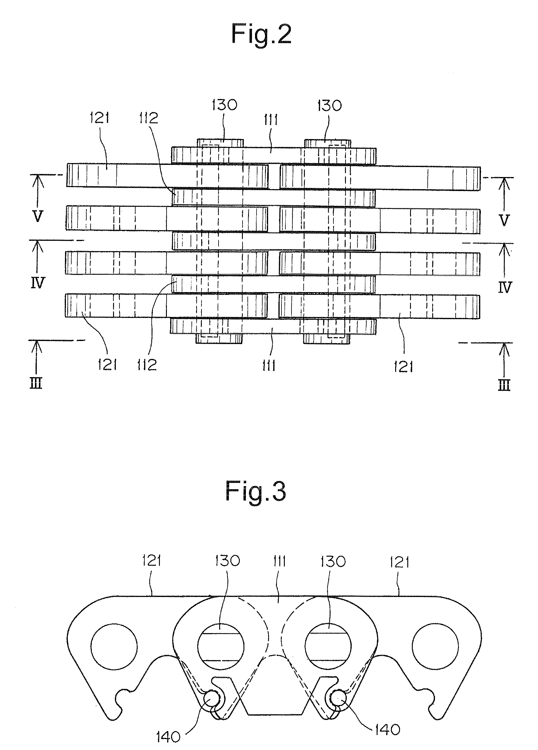
[0008]Each guide plate has two cutout portions, one cutout portion being located adjacent each of the engagement pins attached to the guide plate. Both of the cutout portions of each guide plate are located between the engagement pins, and enable portions of the guide plates to which the engagement pins are connected to deform and thereby absorb loads generated on abutment of the engagement pins with sprocket teeth. A recess is formed in each outer engagement surface of each guide row plate, and the engagement pins of each guide row extend through the recesses in the guide row plates thereof. These recesses partially surround the engagement pins. They only provide clearance for the engagement pins, but are sufficiently deep that they also allow abutment of the outer engagement surfaces of the teeth of the guide row plates with sprocket teeth as the guide plates deform following abutment of the engagement pins with the sprocket teeth.
[0014]It is also preferable that the strength of each said guide plate be smaller than the strength of each said guide row plate and each said joint row plate. When the strength of each guide plate is made smaller than that of each guide row plate and each joint row plate, the deformable cutout portions of the guide plates more easily exhibit a cushioning action reducing impact noise and impact force, and also allow the guide plates to absorb and reduce vibration noise due to characteristic frequencies of the guide row plates and the joint row plates.

Problems solved by technology

However, the conventional chain does not suppress impact noise and impact force sufficiently well to satisfy the increasing demand for noise reduction.
Furthermore the conventional chain is subject to premature wear at the locations at which the impact forces are concentrated.

Method used


Image

  • Silent chain
  • Silent chain
  • Silent chain

Examples


Embodiment Construction

[0023]Briefly, in the silent chain of the invention, engagement pins connecting opposed guide plates have outer surfaces which protrude beyond the outer engagement surfaces of the guide row plates, and therefore abut sprocket teeth before the sprocket teeth are engaged by the guide row plates. Cutout portions of the guide plates allow the guide plates to deform and thereby absorb loads generated as the engagement pins abut the sprocket teeth. Recesses in the outer engagement surfaces of the guide row plates provide clearance for the engagement pins, and allow abutment of the outer engagement surfaces of the guide row plates with sprocket teeth. Recesses in the inner flanks of the joint row plates also provide clearance for the engagement pins, and allow deformation, reducing the load on the joint row plates. As a result, impact noise and impact forces are significantly reduced, and the useful life of the silent chain is extended.

[0024]The invention can be embodied in silent chains o...


PUM


Abstract

In a silent chain having interleaved guide rows and joint rows, guide plates at the outer sides of the guide rows are connected by engagement pins which extend through overlapping recesses formed on the outer flanks of the guide row plates, and on the inner flanks of the joint row plates. The engagement pins contact sprocket teeth before the outer flanks of the guide row plates contact the sprocket teeth. Cutouts formed in the guide plates adjacent the engagement pins allow the guide plates to deform and thereby absorb the impact imparted to the engagement pins by the sprocket teeth.

Description

CROSS-REFERENCE TO RELATED APPLICATION[0001]This application claims priority on the basis of Japanese patent application 2007-319611, filed Dec. 11, 2007. The disclosure of Japanese application 2007-319611 is hereby incorporated by reference.FIELD OF THE INVENTION[0002]The invention relates silent chains for use in power transmission mechanisms, transfer mechanisms, and the like. Such chains have applications in machinery, including industrial machinery, as well as automotive applications. Although the invention is not limited to automotive applications, it has particular advantages when used as a timing chain for transmission of power from a crankshaft to one or more camshafts in an automobile engine, because the chain according to the invention includes features which reduce engagement noise generated as the chain comes into engagement with a sprocket, and which increase the useful life of the chain.BACKGROUND OF THE INVENTION[0003]A typical silent chain is composed of alternating...

Claims


Application Information

Patent Timeline
Patent Type & Authority Applications(United States)
IPC IPC(8): F16G13/04
CPCF16G13/04
Inventor SONODA, MASATOSHIMORIMOTO, TAKAYUKI
Owner TSUBAKIMOTO CHAIN CO
Learn More