Bastions for Force Protection and Military Applications

a technology for military applications and bastions, applied in the field of bases, can solve the problems of destroying the protection afforded, failing to meet the requirements of fire resistance, and prior art protection barriers suffering from a number of additional drawbacks, and achieve the effect of improving the protection offered

Inactive Publication Date: 2009-06-18
CHRISTMAN RYAN +2
View PDF26 Cites 4 Cited by
  • Summary
  • Abstract
  • Description
  • Claims
  • Application Information

AI Technical Summary

Benefits of technology

[0008]The expanded metal mesh or knitted wire mesh lining may withstand a flame thrower attack successfully, without losing particulate filling material through the openings. At the same time the expanded metal mesh or knitted wire mesh lining admits rooting of plants, which helps mitigate the visual impact of the bastions in the cities. Given the nature of the mesh, the plants will grow over the bastions, changing the hard appearance to look as natural fences melding them with the landscape.
[0011]The infill continuity results in cavities or caverns created by impact of projectiles being filled by material coming from both damaged and adjacent cells, thus, improving the protection offered by the bastion.
[0012]The bastion may further include a pinned connection system that allows continuity of cells at different heights, and thus, for the possibility of deployment in sloped terrain.

Problems solved by technology

This structure was rapidly deployable but its main failing was its lack of fire resistance.
Use of flame throwers, incendiary bombs, Molotov cocktails and even tracer bullets of machine guns (one every seven in a belt loader) in combat situations destroys the protection afforded by this conventional bastion by igniting its lining or sand bags defenses.
Prior art protection barriers suffer from a number of additional drawbacks.
Visual impact of prior art protection barriers is unsuitable for deployment within cities and the systems do not provide any concealment option.
Deployment for long periods of time is also problematic given that barriers are exposed to environmental agents such as fungus, and UV attacks, that rapidly deteriorate them.
Further, prior art protection barriers require intensive maintenance.

Method used


Image

  • Bastions for Force Protection and Military Applications
  • Bastions for Force Protection and Military Applications
  • Bastions for Force Protection and Military Applications

Examples


Embodiment Construction

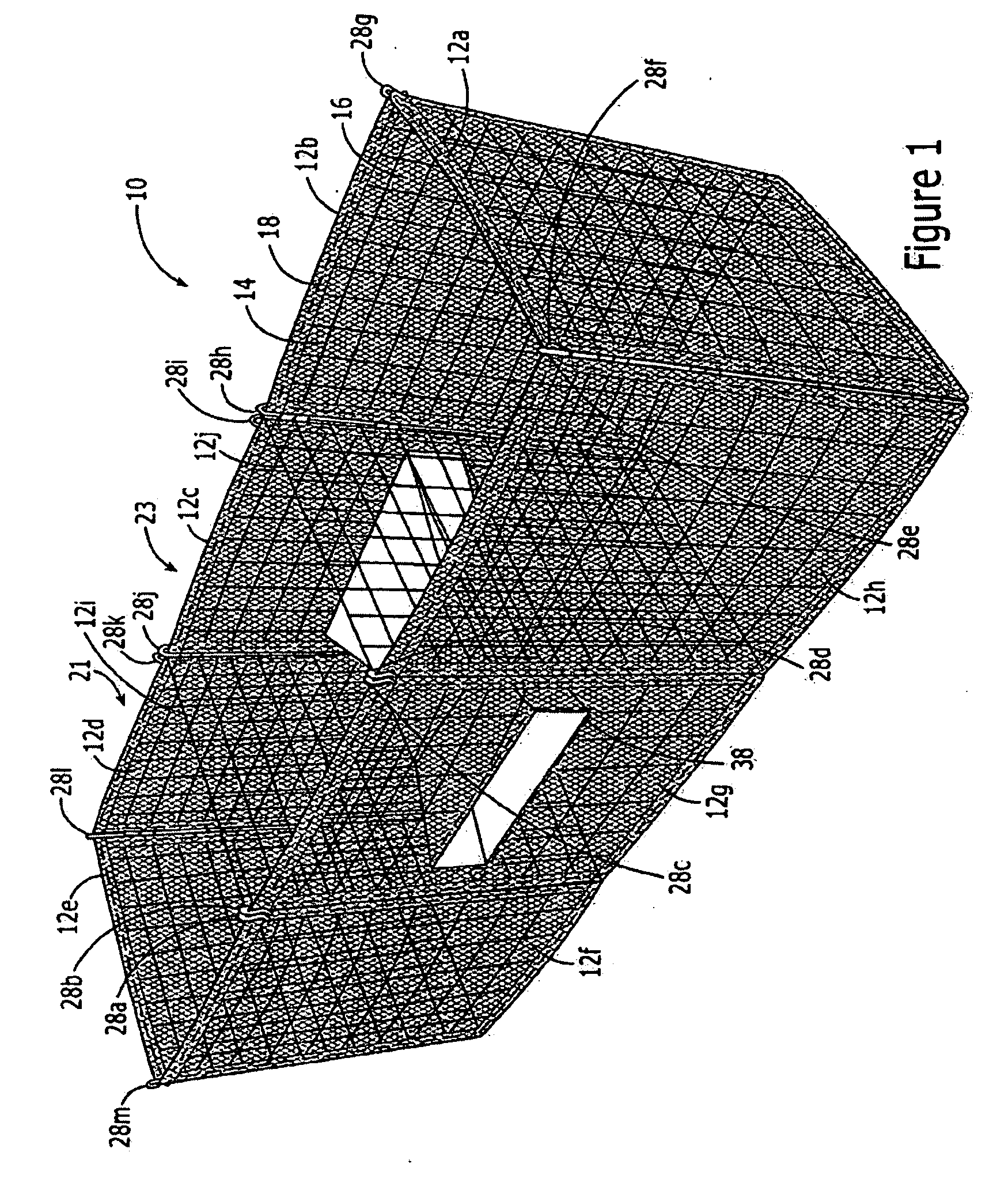
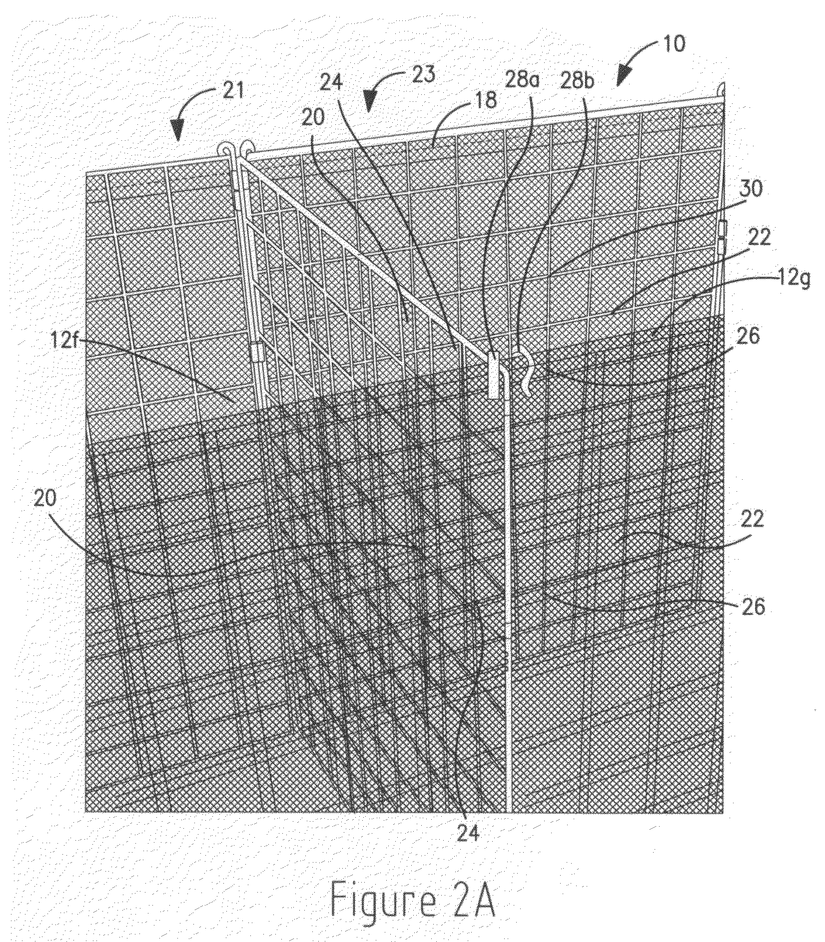
[0042]The basic components of an exemplary embodiment of a bastion of the present invention, generally designated 10, are panels 12a-12j. The panels 12a-12j may be made, for example, from a welded wire frame including wires 14 having, for example, diameters between 3 mm and 8 mm. The wires 14 may, for example, have a rectangular pattern with center to center distance depending on load, for example, 5 cm to 20 cm. The wires 14 may be lined with a screen mesh 16 of expanded metal or wire knitted mesh, stitched to the wire frame or connected using staples 18. Alternatively, the panels 12a-12j may be configured without a mesh. However, in this case the wires 14 are spaced close together so as to prevent a filler, used to fill the bastion 10, such as sand crushed rocks, granulars, etc., from spilling out.

[0043]In the example embodiment of the present invention illustrated in FIG. 1, exterior panels 12a-12h and interior panels 12i and 12j form a three-cell structure of reticular pattern. ...


PUM


Abstract

A bastion including one or more free-standing structures for use in, for example, military applications and for force protection. The free-standing structures are made up of a plurality of interconnected fire resistant mesh covered wire panels and are filled with, for example, sand, crushed rock or granular materials.

Description

[0001]This application is a continuation-in-part of, and claims priority of the filing date of, U.S. Ser. No. 10 / 879,678, filed Jun. 29, 2004, and presently pending.FIELD OF THE INVENTION[0002]The invention relates to a bastion. More particularly, the invention relates to a multiple panel-based bastion system, Which can be used, for example, for military applications and force protection.BACKGROUND OF THE INVENTION[0003]The use of bastions has been traditional ever since Roman times. In the seventeenth and eighteenth centuries it took the form of wicker baskets filled with earth or stones. In the early twentieth century, sand bags were used. In the later twentieth century bastions took the form of gabion structures lined with geo-textiles.[0004]This latter application, was basically the use of elements originally devised for civil works applied to the military use. This structure was rapidly deployable but its main failing was its lack of fire resistance. At best, a fire retardant c...

Claims


Application Information

Patent Timeline
Patent Type & Authority Applications(United States)
IPC IPC(8): E04C2/52E04H12/08
CPCE02D29/0208E01F8/025
Inventor CHRISTMAN, RYANGALLEGO, JORGE ENRIQUEGIRALDO, CESAR
Owner CHRISTMAN RYAN
Why Eureka
Try Eureka