Coupling structure of steam generator in washing device

a technology of coupling structure and washing device, which is applied in the direction of cleaning using liquids, separation processes, instruments, etc., can solve the problems of fire, large quantity of washing water required for washing mode, and several problems of related art steam generators for washing devices, so as to avoid fire risk

Active Publication Date: 2009-06-18
LG ELECTRONICS INC
View PDF5 Cites 14 Cited by
  • Summary
  • Abstract
  • Description
  • Claims
  • Application Information

AI Technical Summary

Benefits of technology

[0035]As described above, the coupling structure of the steam generator according to the present invention has the following advantages.
[0036]First, since the portion of the steam generator, where the temperature fuse is positioned, is higher than the height of the heater, it is possible to avoid a risk of fire of the steam generator, which may be caused by overheat of the heater.
[0037]In addition, even though the heater or the washing device is slanted toward any one side during the manufactur...

Problems solved by technology

However, a problem arises in that a great quantity of washing water is required for the washing mode.
However, the related art steam generator for a washing device has several problems.
As a result, fire occurs.
For this reason, a problem arises in that the corresponding portion of the case 1 is thermally deforme...

Method used


Image

  • Coupling structure of steam generator in washing device
  • Coupling structure of steam generator in washing device
  • Coupling structure of steam generator in washing device

Examples


first embodiment

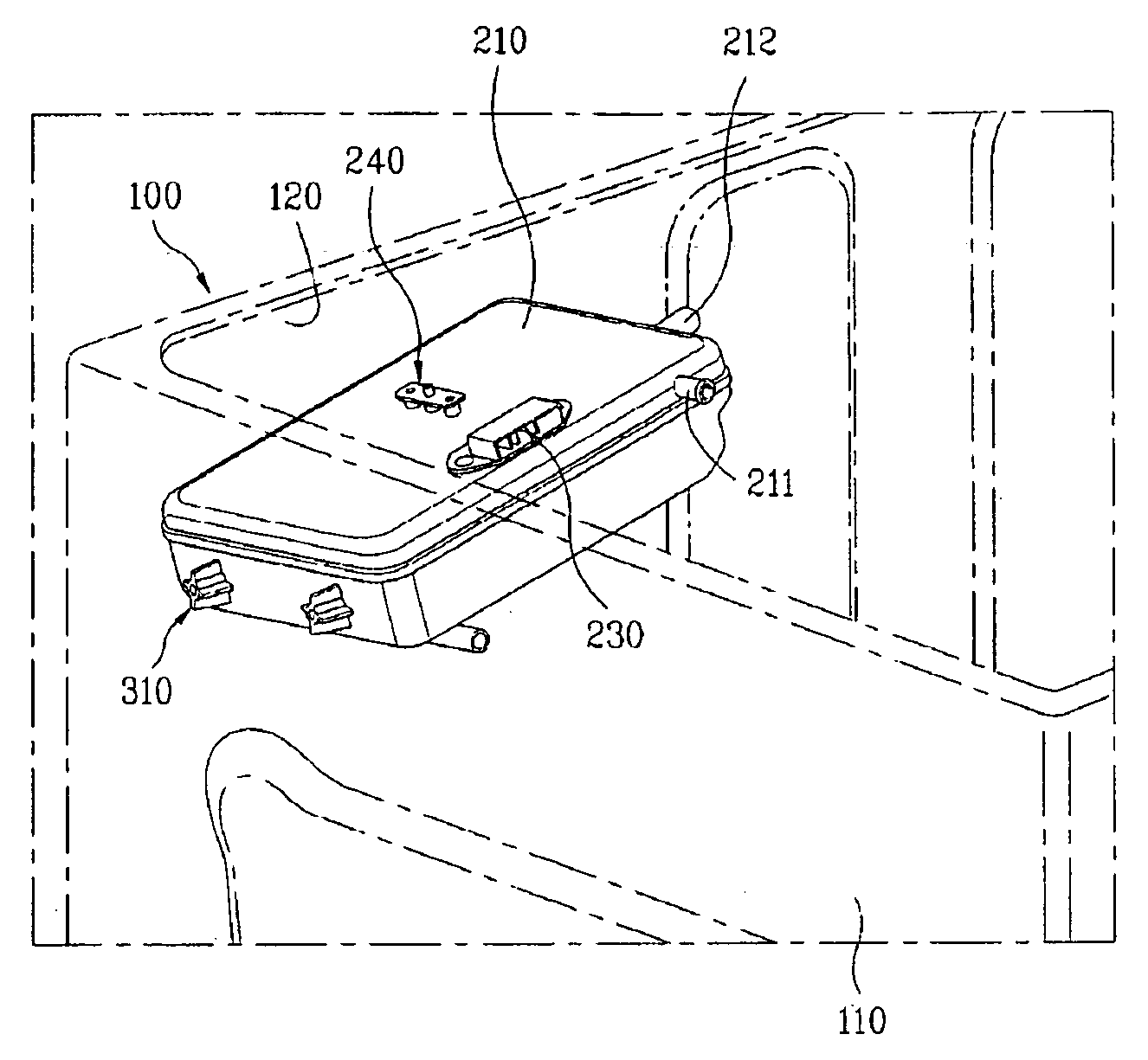
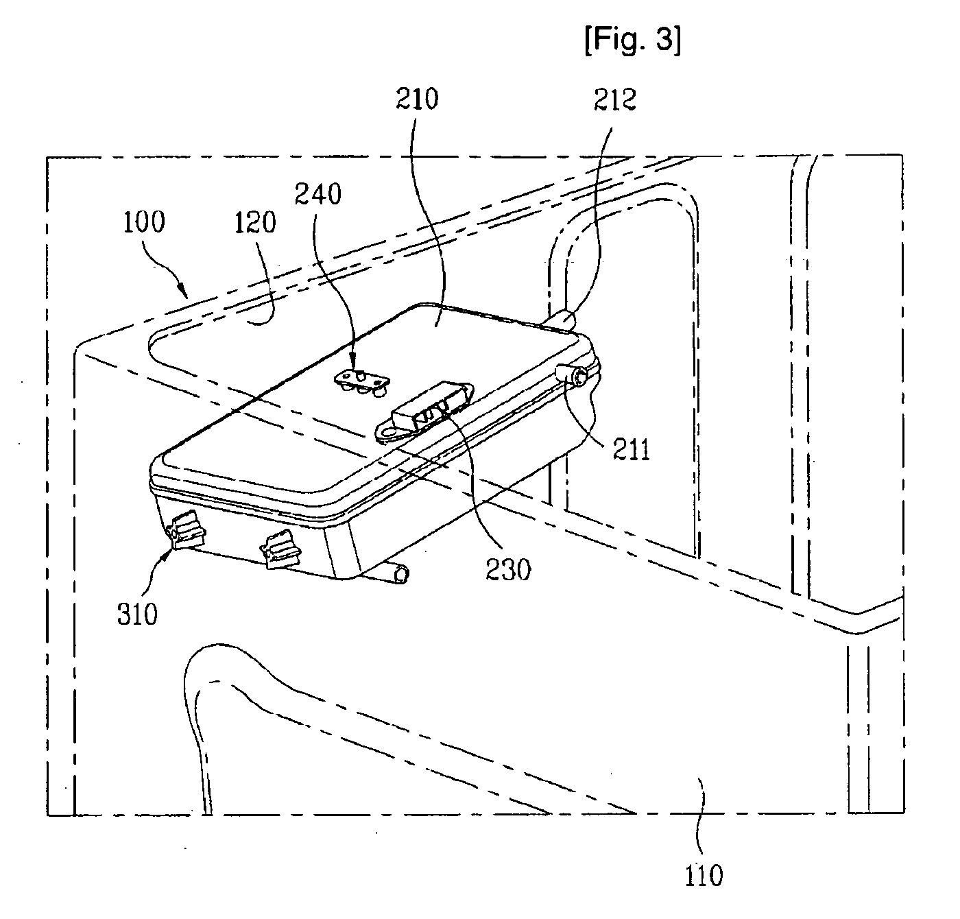
[0053]FIG. 3 and FIG. 4 illustrate a coupling structure of a steam generator for a washing device according to the present invention.

[0054]As shown in FIG. 3 and FIG. 4, the coupling structure of the steam generator for the washing device according to the, first embodiment of the present invention includes a coupling portion provided between a main body 100 constituting appearance of the washing device and the steam generator.

[0055]The main body 100 of the washing device includes a back cover 110 constituting a rear surface, and a side cabinet 120 constituting both sides.

[0056]The steam generator includes a case 210, a heater 220, and a temperature fuse 250.

[0057]The case 210 constitutes appearance of the steam generator and is provided inside the main body 100 of the washing device. The case 210 has a rectangular box shape.

[0058]A water supply pipe 211 is formed at one side of the case 210. The water supply pipe 211 is supplied with water for generating steam. A steam discharge pip...

second embodiment

[0090]First, FIG. 5 and FIG. 6 illustrate the coupling structure of the steam generator for the washing device according to the present invention.

[0091]The coupling portion of the steam generator according to the second embodiment of the present invention is provided between the rear surface of the case 210 and the inner wall of the side cabinet 120 of the main body 100 constituting the washing device.

[0092]In this case, the coupling portion of the steam generator according to the second embodiment of the present invention has the same shape as that of the coupling portion of the steam generator according to the first embodiment of the present invention.

[0093]In other words, the coupling portion includes a pair of first coupling projections 310 respectively projected at both sides on the rear surface of the case 210. Ends of the first coupling projections 310 coupled with the inner wall of the side cabinet 120 are slanted toward their base so that they are to be gradually projected ...

third embodiment

[0097]Meanwhile, FIG. 7 and FIG. 8 illustrate the coupling structure of the steam generator for the washing device according to the present invention.

[0098]The coupling portion of the steam generator according to the third embodiment of the present invention is provided between any one long side (hereinafter, referred to as “case side”) of the circumference of the case 210 constituting the steam generator and the inner wall of the back cover 110 of the main body 100 constituting the washing device.

[0099]In particular, the coupling portion of the steam generator according to the third embodiment of the present invention includes a pair of second coupling projections 320 respectively projected at both sides of the case 210 and coupled with the inner wall of the back cover 110.

[0100]At this time, the coupling portion between any one of the second coupling projections 320, which is provided to relatively adjoin the temperature fuse 250, and the inner wall of the back cover 110 is higher...


PUM


Abstract

A steam generator for a laundry machine is disclosed, in which the power supplied to a heater is cut off before a water level of water used to generate steam is lower than an end of the heater, thereby avoiding a risk of fire. The steam generator includes a case coupled with the main body of the laundry machine. A heater is provided inside the case. A temperature fuse is provided inside the case when a coupling portion couples the case with the main body of the temperature fuse is configured to be higher than the heater based on a horizontal line.

Description

TECHNICAL FIELD[0001]The present invention relates to a washing device, and more particularly, to a coupling structure of a steam generator in a washing device, in which steam is generated to be used for washing and drying functions.BACKGROUND ART[0002]In general, examples of a washing device include a pulsator type washing machine, a drum washing machine, a washing machine having a drying function, and a drying machine. The pulsator type washing machine is provided with a drum built in a vertical direction. The drum washing machine is provided with a drum laid in a horizontal direction. The drying machine carries out only a drying function of clothes.[0003]Among the examples of the washing device, the pulsator type washing machine, the drum washing machine, and the washing machine having a drying function have carried out a washing mode using washing water.[0004]However, a problem arises in that a great quantity of washing water is required for the washing mode. In this respect, ef...

Claims


Application Information

Patent Timeline
IPC IPC(8): D06F39/04D06F39/08F22B1/28H01H37/76
CPCD06F39/008F22B1/284D06F39/12A47L15/4234D06F37/42D06F39/04D06F2103/52
Inventor PARK, SEOG KYU
Owner LG ELECTRONICS INC
Why Eureka
Try Eureka