Hot press apparatus and a hot press method for thin plate-like workpieces

a technology of hot press and workpiece, which is applied in the direction of veneer presses, drying machines with progressive movements, applications, etc., can solve the problem of workpiece position deviation

Inactive Publication Date: 2009-06-18
MIKADO TECHNOS
View PDF1 Cites 21 Cited by
  • Summary
  • Abstract
  • Description
  • Claims
  • Application Information

AI Technical Summary

Benefits of technology

[0038]Since the present invention takes the above-mentioned construction, the film member-horizontally holding member is fitted to substantially horizontally hold the heat-resistant and stretchable film member, while preventing the film member from hanging down and to keep substantially constant the position, as viewed in the horizontal direction, where the heat-resistant and stretchable film member is held by the film member-horizontally holding member. Accordingly, the heat-resistant and stretchable film member can be brought into contact with the upper face of the work piece without being positionally deviated. In addition, after the workpiece is preheated, the workpiece is subjected to a predetermined hot processing with the heat-resistant and stretchable film member by applying pressure to the heat medium inside the heat medium-filling space in the state that the heat-resistant and stretchable film member is located and held, while being prevented from expanding radially outwardly at the outer periphery. Thus, the workpiece can be hot pressed precisely under a uniform pressure without the hot pressing position for the workpiece being deviated.

Problems solved by technology

The present inventor discovered, however, that when the thickness of thin film is decreased, a central portion of the thin film hangs down in a bell shape by the weight of the heat medium, so that the lower face of the thin film does not uniformly contact the upper face of the substrate and consequently the workpiece may be positionally deviated.

Method used


Image

  • Hot press apparatus and a hot press method for thin plate-like workpieces
  • Hot press apparatus and a hot press method for thin plate-like workpieces
  • Hot press apparatus and a hot press method for thin plate-like workpieces

Examples


specific embodiments

Explanation of Specific Embodiments

[0094]In the following, specific embodiments of the present invention will be explained along with the attached drawings. Such embodiments are merely illustrative of the invention, and it goes without saying that the present invention is not limited to the illustrated embodiments.

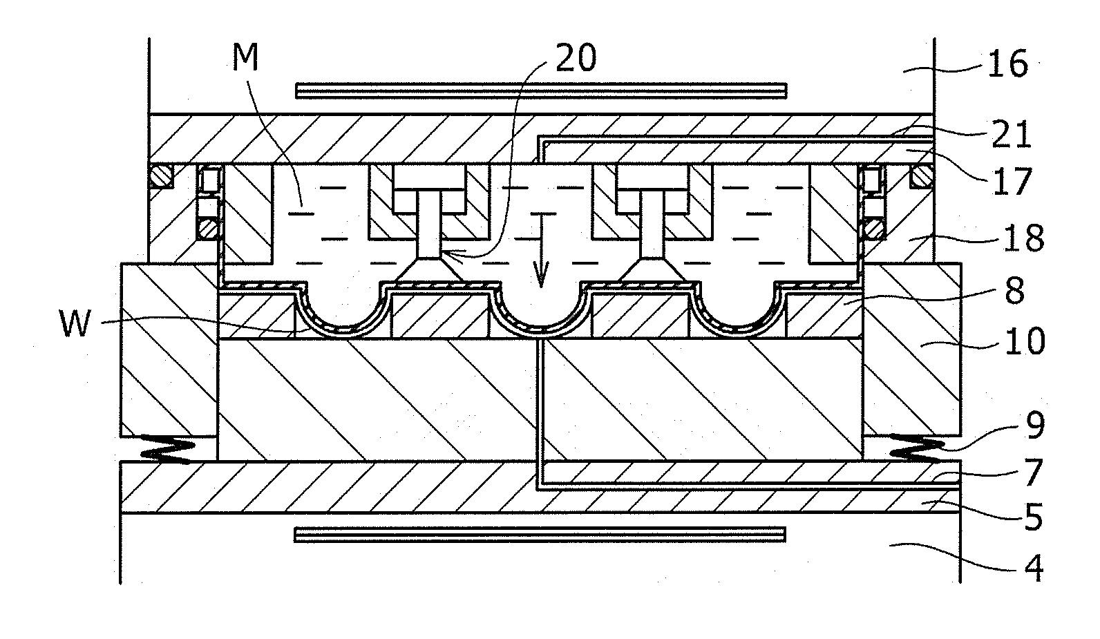
[0095]FIGS. 6 and 7 illustrate one embodiment of the hot press apparatus according to the present invention. In FIG. 6, a rail 2 is provided on an upper face of a base 1, a slide table 3 is arranged laterally movably on the rail 2, and a lower heating plate 4 is placed on the slide table 3 via posts and an adiabatic plate. Soaking plates 5 and 6 are arranged on the lower heating plate 4 as shown, an air ejecting path 7 is provided in the soaking plates 5 and 6 as shown, and a workpiece W is peeled from a lower mold member 8 after the press working by ejecting a high-pressure compressed air through the air ejecting path 7, and is then taken outside. In this embodiment, the ...


PUM

PropertyMeasurementUnit
thicknessaaaaaaaaaa
thicknessaaaaaaaaaa
heat-resistantaaaaaaaaaa

Abstract

A hot press apparatus for hot pressing a thin plate-like workpiece, includes a base 1, lower and upper heating plates 4, 16, a flat lower mold member 8, lower and upper frame members 10, 18, a workpiece taking-out unit 7, an upper press plate 12, a heat-resistant and stretchable film member 19 covering the lower end portion of the upper frame member 18, a heat medium M filled in a heat medium-filling space above the film member, and a driving unit 13. A film member-horizontally holding member 20 substantially horizontally holds the film member while preventing the film member from hanging, while keeping it at a substantially constant position as viewed in a horizontal direction. The workpiece is hot pressed with the film member by applying pressure to the heat medium inside the heat medium-filling space while the film member is prevented from expanding radially outwardly at an outer periphery thereof.

Description

INCORPORATION BY REFERENCE[0001]The convention priority of a Japanese patent application No. 2007-323592 filed on Dec. 14, 2007 (now U.S. Pat. No. 4,176,817) is claimed herein, and its entire contents are incorporated herein by reference.BACKGROUND OF THE INVENTION[0002](1)Field of the Invention[0003]The present invention relates to a hot press apparatus and a hot press method for thin plate-like workpieces.[0004](2) Description of the Related Art[0005]In the press working steps for thin plate-like workpieces, for example, for bonding substrates, they are required to be formed in a uniform thickness at a high precision with a uniform pressure. Meanwhile, the thin plate-like workpieces themselves may be concave-and-convex, wavy or the like, and they are demanded to be plane-pressed under a uniform pressure.[0006]In order to accomplish the above object, a hot press is proposed, which is provided with a thin-film container that is filled with a fluid heat medium and is positioned at a ...

Claims


Application Information

Patent Timeline
Patent Type & Authority Applications(United States)
IPC IPC(8): B30B15/34
CPCB29C51/28B29C51/42B29C51/428B30B15/34B29C63/16B30B5/02B29C63/04
Inventor ITO, HIDETOSHI
Owner MIKADO TECHNOS
Why Eureka
Try Eureka