Papermaking mold and fiber molded

a papermaking mold and fiber molded technology, applied in the field of papermaking molds and fiber molded articles, can solve the problems of becoming more difficult to supply raw material slurry and difficult to produce fiber molded articles with closely spaced plate-like projections

Inactive Publication Date: 2009-06-18
KAO CORP
View PDF0 Cites 4 Cited by
  • Summary
  • Abstract
  • Description
  • Claims
  • Application Information

AI Technical Summary

Benefits of technology

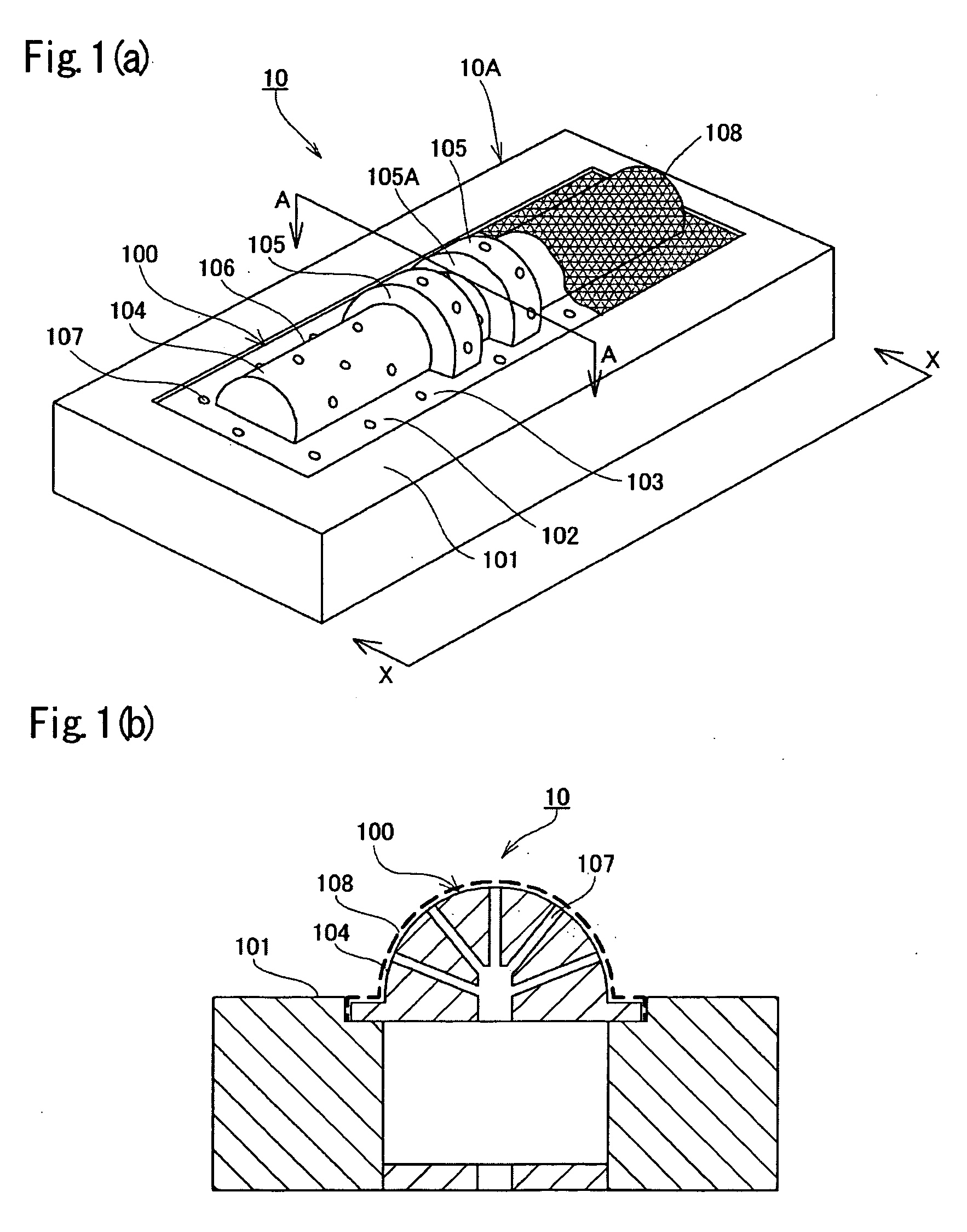
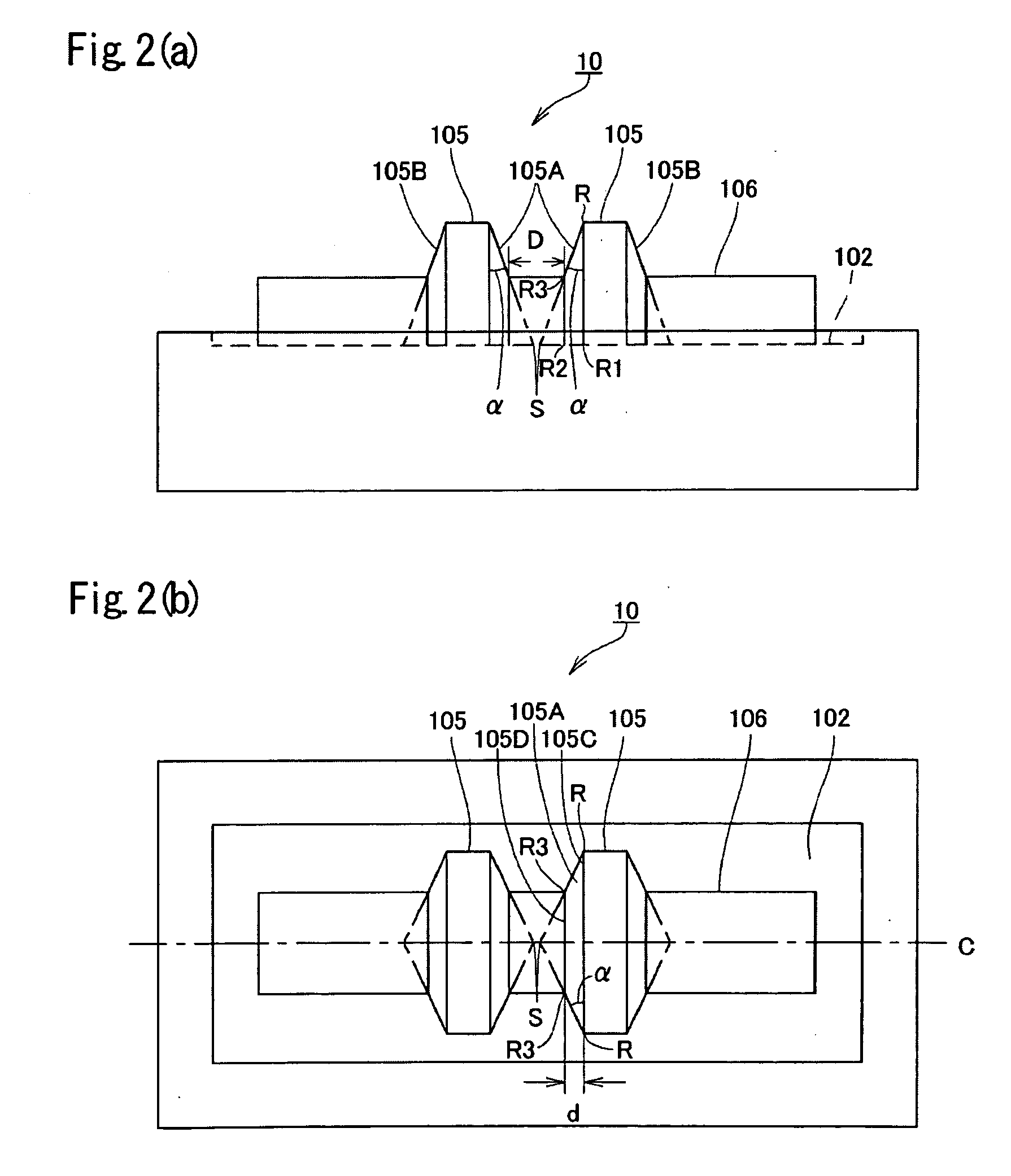
[0058]Since the papermaking mold 10 having the plate-like projections 105 has a circular conical surface to form the facing inner sides 105A of the projections 105, the papermaking material is allowed to be duly deposited on the wire 108 between the plate-like projections 105. Accordingly, a crack-free fiber molded article can be produced even if the plate-like projections are closely spaced.
[0059]An embodiment of the drying / pressing mold that can be used in combination with the papermaking mold 10 in the production of a fiber molded article will then be described.
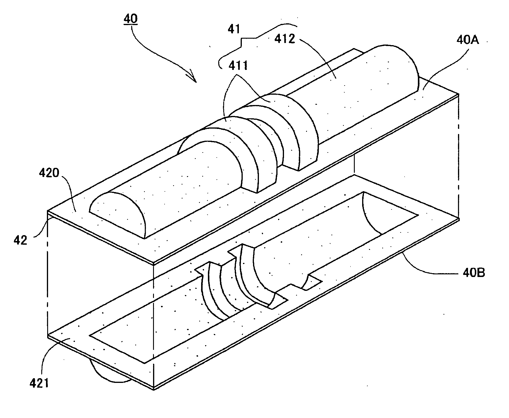
[0060]As shown in FIG. 3, the drying / pressing mold of the present embodiment has a female member 20 and a male member 30 for drying and pressing. The female member 20 and the male member 30 are configured to be butted together to form a clearance therebetween defining the outer contour of a fiber molded article 40A to be produced.
[0061]As shown in FIGS. 3 and 4, the female member 20 has a concave forming part 200 and a butting face 201. The concavity of the concave forming part 200 is an inversion of the outer contour (convexity) of the fiber molded article 40A to be produced. The forming part 200 has its surface coated with a fluororesin. The forming part 200 has a recess 202 from the butting face 201, the recess 202 being shaped to accommodate the flange 42 of the fiber molded article 40A. The forming part 200 has a concavity relative to the base surface (bottom) 203 of the recess 202. The concavity is composed of depressions 204 and a depression 205 corresponding to the plate-like projections and the columnar projection, respectively, of the fiber molded article 40A. The depressions 204 corresponding to the plate-like projections and the depression 205 corresponding to the columnar projection are configured to have their semicircular cross-sections aligned on the same axis C (see FIG. 4(b)). The recess 202, the depressions 204 corresponding to the plate-like projections and the depression 205 corresponding to the columnar projection define a space-forming wall (described later). The female member 20 has, in the inside thereof, gas / liquid passageways 206 open on the surface of the forming part 200.
[0062]The adjacent sides (inner sides) 204A of the adjacent depressions 204 corresponding to the plate-like projections are each formed of a part of a circular conical surface. While the conical surface as the inner side 204A preferably has its point S positioned on the axis C (the axis on which the center of the outer periphery 204C and the center of the inner periphery 204D of the depression 204 for forming the plate-like projection is positioned), the point S may be deviated from the axis C or the base surface 203 unless the effects of the present invention are affected.
[0063]The male member 30 is configured so that a wet fiber mat formed on the papermaking mold 10 is put thereon and dried. Accordingly, the male member 30 has a forming part 300 the contour of which is equal to that of the wire part 100 (exclusive of the wire) of the papermaking mold 10 as shown in FIGS. 3 and 5. The forming part 300 has its surface coated with a fluororesin. The forming part 300 has a base surface 301 and a convexity 302 projecting from the base surface 301. The convexity 302 includes a columnar projection 304 having a semicircular cross-section and lying sideways on the base surface 301 and two plate-like projections 303 each having a semicircular cross-section arranged at predetermined positions at a predetermined spacing in the longitudinal direction of the columnar projection. The plate-like projections 303 each have a lager diameter than that of the columnar projection 304. The semicircular cross-section of each of the plate-like projections 303 and that of the columnar projection 304 have their center on the same axis. Both ends of the columnar projection 304 stick longitudinally outward from the outer sides 303B of the plate-like projections 303. The male member 30 has, in the inside thereof, gas / liquid passageways 305 open on the base surface 301 and the outer surface of the convexity 302 of the forming part 300.

Problems solved by technology

However, it becomes more difficult to sufficiently supply the raw material slurry to a closer space between the plate-like projections in the formation of a wet fiber mat, i.e., a fiber molded article precursor.
As a result, that part of the resulting fiber mat may be thinner than designed, or a fiber mat may not be formed in that part.
Therefore, it has been difficult to produce a fiber molded article having closely spaced plate-like projections.

Method used


Image

  • Papermaking mold and fiber molded
  • Papermaking mold and fiber molded
  • Papermaking mold and fiber molded

Examples


example 1

[0168]A fiber mat as a fiber molded article precursor having two plate-like projections the facing inner sides thereof were formed of a part of a circular conical surface was produced using a papermaking mold shown in FIG. 30.

(1) Material

[0169]Organic fiber (recycled newspaper), inorganic fiber (carbon fiber), inorganic powder (graphite powder), thermosetting resin (phenol resin), and thermoexpandable particles were blended at a ratio of 4:4:76:12:4 by mass and dispersed in water to prepare a slurry having a solids content of about 3% by mass.

(2) Papermaking Mold

[0170]Material of mold main body: aluminum alloy

Main dimensions of papermaking mold:

L=288.5 mm; W1=13 mm; W2=9 mm; D=3 mm; A1=32.4 mm; A2=32.4 mm; A3=20 mm; d1=0.65 mm; d2=0.65 mm; α=3°

Wire: stainless wire; wire diameter=0.19 mm; #40 mesh

(3) Dewatering Condition

[0171]Dewatering system: suction by a waterproof vacuum cleaner

Dewatering time: 60 seconds

Water content after dewatering: 30-80%


PUM

PropertyMeasurementUnit
distanceaaaaaaaaaa
thicknessaaaaaaaaaa
thicknessaaaaaaaaaa

Abstract

A papermaking mold 10 includes a mold main body 10A having a wire part and a wire 108 disposed on the wire part. The wire part has a base surface 102, a columnar projection 106 lying sideways on the base surface 102, and at least two plate-like projections 105 at predetermined positions at a predetermined spacing in the longitudinal direction of the columnar projection 106. The facing inner sides 105A of every adjacent two of the plate-like projections 105 are each formed of a part of a circular conical surface or a part of a hyperboloid.

Description

TECHNICAL FIELD[0001]The present invention relates to a papermaking mold and a fiber molded article.BACKGROUND ART[0002]The common assignee of the present invention has proposed a technique of producing a fiber molded article in JP 2005-290600A. The technique is pertinent to a method in which a wet mat of fibers is prepared by papermaking processing using a raw material slurry containing a fibrous material such as inorganic fiber and organic fiber, dewatering the wet fiber mat, followed by drying and pressing to make a fiber molded article with a desired contour.[0003]JP 2005-290600A diagrammatically shows in its FIG. 1, etc. a papermaking mold having a wire part, the wire part comprising a base surface, a semicylindrical columnar projection lying sideways on the base surface, and two semicylindrical plate-like projections arranged at a predetermined position at a predetermined spacing in the longitudinal direction of the columnar projection.[0004]In making a fiber molded article as...

Claims


Application Information

Patent Timeline
Patent Type & Authority Applications(United States)
IPC IPC(8): D21J3/00
CPCD21J3/10D21J7/00D21J5/00D21J3/00D21J3/12
Inventor OOTAKI, SEITAKAGI, YOSHIMASAOSAKI, MASAYUKIAHIKO, SHUU
Owner KAO CORP
Why Eureka
Try Eureka