Low Chromium Stainless Steel Superior in Corrosion Resistance of Multipass Welded Heat Affected Zones and Its Method of Production

Active Publication Date: 2009-04-16
NIPPON STEEL & SUMIKIN STAINLESS STEEL CORP
View PDF0 Cites 4 Cited by
  • Summary
  • Abstract
  • Description
  • Claims
  • Application Information

AI Technical Summary

Benefits of technology

[0012]The present invention has as its first object the provision of optimal low chromium stainless steel preventing deterioration of the corrosion resistance in the weld zones in the case of multipass welding of low chromium stainless steel using martensitic transformation, superior in grain boundary corrosion resistance of multipass weld zones even in harsh corrosive environments such as where coal or iron ore railroad cars are used, simultaneously free from preferential corrosion occurring near weld zone fusion lines, and superior in manufacturability. It has as its second object the provision of high strength low chromium stainless steel superior in the strength-ductility balance according to need.
[0014]Therefore, the inventors engaged in studies to prevent preferential corrosion of the heat affected zones adjoining the weld zones and as a result discovered that the heat affected zones where the massive martensite is formed adjoining the weld zones are exposed to extremely high temperatures, so depending on the welding method, scale is thickly formed at just these locations, the concentration of Cr directly under the scale drops, a so-called Cr-depleted layer is formed, and as a result preferential corrosion similar to knife line attack as a phenomenon occurs. Further, the inventors found that if the content of Ti having an effect on grain boundary corrosion resistance of the multipass weld heat affected zones increases, it becomes a cause of surface defects due to the precipitation of TiN, so it is necessary to control the product of the concentrations of Ti and N to 0.004 or less. Further, the inventors engaged in studies to improve the corrosion resistance of the weld heat affected zones and, further, to prevent the drop in weld zone toughness and as a result discovered that the object could be achieved by designing the ingredients to satisfy the following formula (A) describing the austenite stability and achieving suitable phase stability.γp(%)=420×C %+470×N %+23×Ni %+9×Cu %+7×Mn %−11.5×Cr %−11.5×Si %−12×Mo %−23×V %−47×Nb %−49×Ti %−52×Al %+189≧80  (A)
[0015]γp (gamma potential) is an indicator for evaluating the stability of austenite. Simultaneously, it is an indicator expressing the ease of formation of martensite.
[0016]Further, the inventors discovered that in the production of stainless steel designed in ingredients as above, when controlling the heating temperature in the hot rolling process of cast slabs to a temperature where the austenite single phase region or amount of 6-ferrite exceeds 50%, it is possible to produce low chromium stainless steel free from edge cracking.
[0018]Therefore, the inventors engaged in studies to increase the strength of low chromium ferritic stainless steel, whereupon they discovered that in producing stainless steel designed in ingredients to improve the corrosion resistance of the heat affected zones adjoining the weld zones, by suitably selecting the heat treatment temperature and soaking time in the heat treatment process of hot rolled plate, it is possible to suitably adjust the metal structure to a two-phase structure of ferrite and martensite in the tempering softening heat treatment process of martensitic structure hot rolled plate and thereby possible to produce high strength chromium stainless steel superior in strength-ductility balance. In particular, this is effective and practical for the case of ingredients suitably containing Nb and Ni and raising the tempering softening resistance. The heat treatment conditions are practically speaking for example a heat treatment temperature of 600 to 800° C. and a soaking time of 2 to 30 hours. By setting a suitable temperature, the desired metal structure can be obtained.

Problems solved by technology

The inventors engaged in in-depth studies to achieve the above object and as a result discovered that to prevent grain boundary corrosion at the weld zones and their vicinities in the case of multipass welding, it is possible to add Ti and Nb stabilizing the carbon and nitrogen causing the occurrence of grain boundary corrosion, but on the other hand the addition of Ti and Nb has no effect in the prevention of preferential corrosion near the weld zone fusion lines.
Further, the inventors found that if the content of Ti having an effect on grain boundary corrosion resistance of the multipass weld heat affected zones increases, it becomes a cause of surface defects due to the precipitation of TiN, so it is necessary to control the product of the concentrations of Ti and N to 0.004 or less.

Method used


Image

  • Low Chromium Stainless Steel Superior in Corrosion Resistance of Multipass Welded Heat Affected Zones and Its Method of Production
  • Low Chromium Stainless Steel Superior in Corrosion Resistance of Multipass Welded Heat Affected Zones and Its Method of Production
  • Low Chromium Stainless Steel Superior in Corrosion Resistance of Multipass Welded Heat Affected Zones and Its Method of Production

Examples


example 1

[0071]Table 1 and Table 2 show invention steels and comparative steels relating to the first pending issue.

[0072]Table 1 shows the steel ingredients of the invention steels and comparative steels by mass %. Steel Material Nos. 1 to 20 are invention steels, while Steel Material Nos. 21 to 26 are comparative steels.

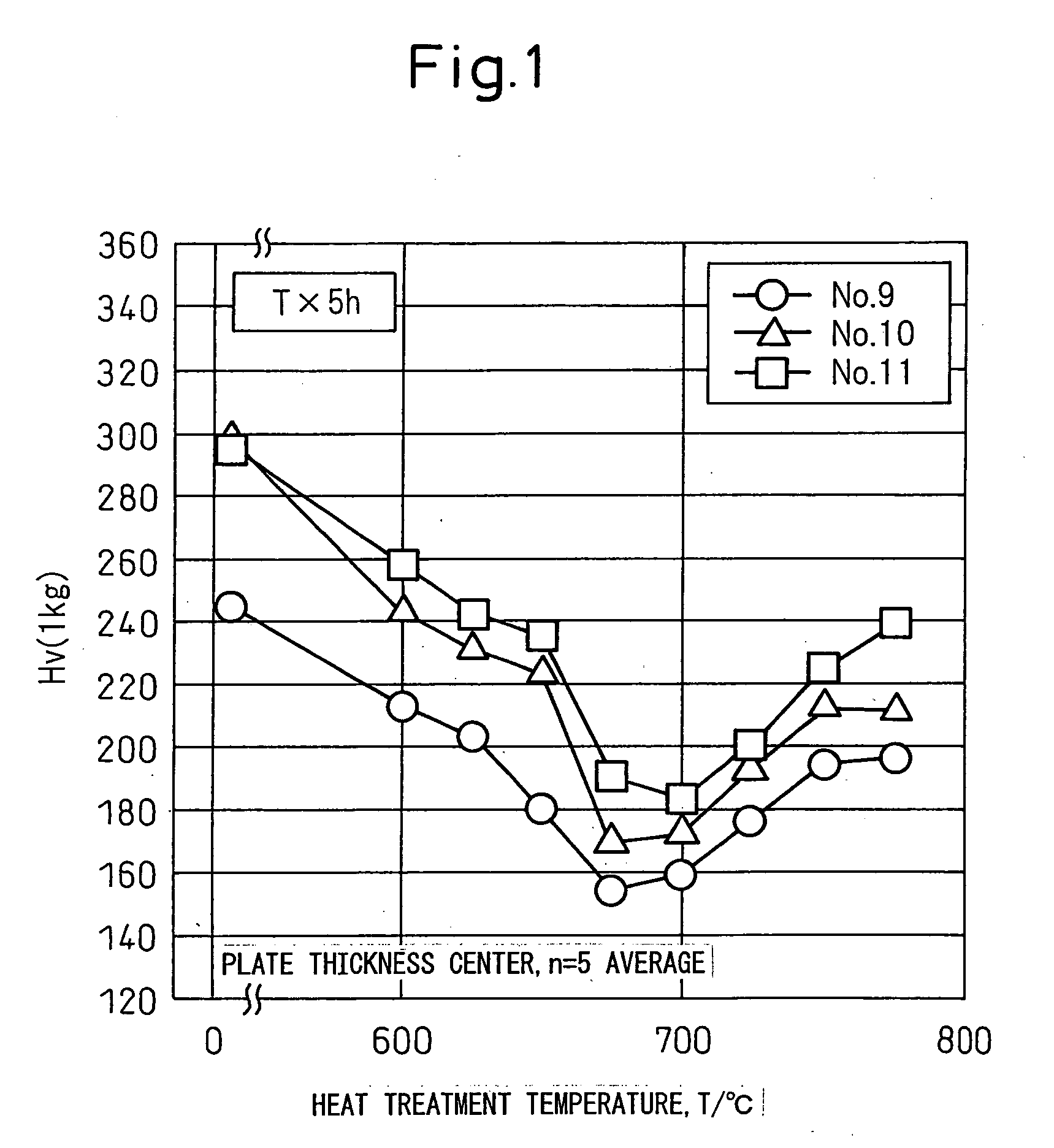
[0073]The vacuum melting method was used to melt cast slabs of the ingredients shown in Table 1 into 40 kg or 35 kg flat ingots. These steels were touched up on their surfaces, then the ingots were heated at 1150° C. to 1250° C. for 1 hour and processed by hot roughing comprised of multiple passes and the following finishing rolling. The end temperature of the hot rolling was 800° C. to 950° C. The hot rolled plates were air cooled, then soaked at a coiling temperature of 700° C. for 1 hour, then air cooled and coiled up for simulated heat treatment so as to obtain hot rolled plates of plate thicknesses of 4 mm. Next, to determine the annealing temperatures of the hot rolle...

example 2

[0093]Table 3 and Table 4 show invention examples and comparative examples relating to the second pending issue.

[0094]Table 3 shows the steel ingredients of the invention steels (Steel Material Nos. 27 to 35) by mass %. The vacuum melting method was used to melt cast slabs of the ingredients shown in Table 3 into 40 kg or 35 kg flat ingots. These steels were touched up on their surfaces, then the ingots were heated at 1150° C. for 1 hour and processed by hot roughing comprised of multiple passes and the following final hot rolling. The end temperature of the hot rolling was 800° C. to 900° C. The hot rolled plates were air cooled, then soaked at a coiling temperature of 500° C. for 1 hour, then air-cooled and coiled up for a simulated heat treatment to obtain hot rolled plate of a plate thickness of 4 mm. Next, to determine the annealing temperature of the hot rolled plate, various ingredients of hot rolled plates were soaked at 575° C. to 850° C. for 5 to 50 hours, then, simulating...


PUM

PropertyMeasurementUnit
Fractionaaaaaaaaaa
Fractionaaaaaaaaaa
Fractionaaaaaaaaaa

Abstract

The present invention provides optimal low chromium stainless steel preventing the deterioration in corrosion resistance at the weld zone in the case of multipass welding, superior in grain boundary corrosion resistance of the weld zone even in a harsh corrosive environment, simultaneously free from preferential corrosion at the heat affected zones near weld fusion lines, and further superior in manufacturability, that is, low chromium stainless steel containing, by mass %, C: 0.03% or less, N: 0.004 to 0.02%, Si: 0.2 to 1%, Mn: over 1.5 to 2.5%, P: 0.04% or less, S: 0.03% or less, Cr: 10 to 15%, Ni: 0.2 to 3.0%, and Al: 0.005 to 0.1%, further containing Ti: 4×(C %+N %) to 0.35%, and having a balance of Fe and unavoidable impurities, having a γp(%) expressed by a predetermined formula satisfying 80 or more, and satisfying Ti %×N %<0.004 as well.

Description

TECHNICAL FIELD[0001]The present invention relates to low chromium stainless steel superior in corrosion resistance of weld zones improving the grain boundary corrosion resistance at the heat affected zones near weld zones in the case of multipass welding, avoiding preferential corrosion occurring at parts adjoining welds near the fusion lines, and able to be used as structural steel etc. for applications of harsh corrosive environments over long periods of time.BACKGROUND ART[0002]Chromium stainless steel with a low chromium content and a low nickel content is extremely advantageous cost-wise compared with austenitic stainless steel such as SUS304 steel, so is suitable for applications of use in large quantities such as structural steels. Such low chromium stainless steel has a ferritic structure or martensitic structure corresponding to the composition of ingredients. In general, ferritic or martensitic stainless steel is inferior in low temperature toughness or corrosion resistan...

Claims


Application Information

Patent Timeline
IPC IPC(8): C22C38/22C22C38/20C22C38/28C21D8/00
CPCC21D6/002C21D8/0263C21D9/46C21D9/50C22C38/58C21D2211/008C22C38/001C22C38/02C22C38/06C21D2211/005
Inventor FUKAYA, MASUHIROTAKAHASHI, AKIHIKOTERAOKA, SHINICHISAKAMOTO, SHUNJI
Owner NIPPON STEEL & SUMIKIN STAINLESS STEEL CORP
Why Eureka
Try Eureka