
Cooling Module

a technology of cooling module and cooling fan, which is applied in the field of cooling module, can solve the problems of insufficient space for a large cooling fan, unsuitable for electronic products with power or noise limitations, and generation of undesired nois

Inactive Publication Date: 2009-06-18
PARTNER TECH
View PDF4 Cites 0 Cited by
  • Summary
  • Abstract
  • Description
  • Claims
  • Application Information

AI Technical Summary

Benefits of technology

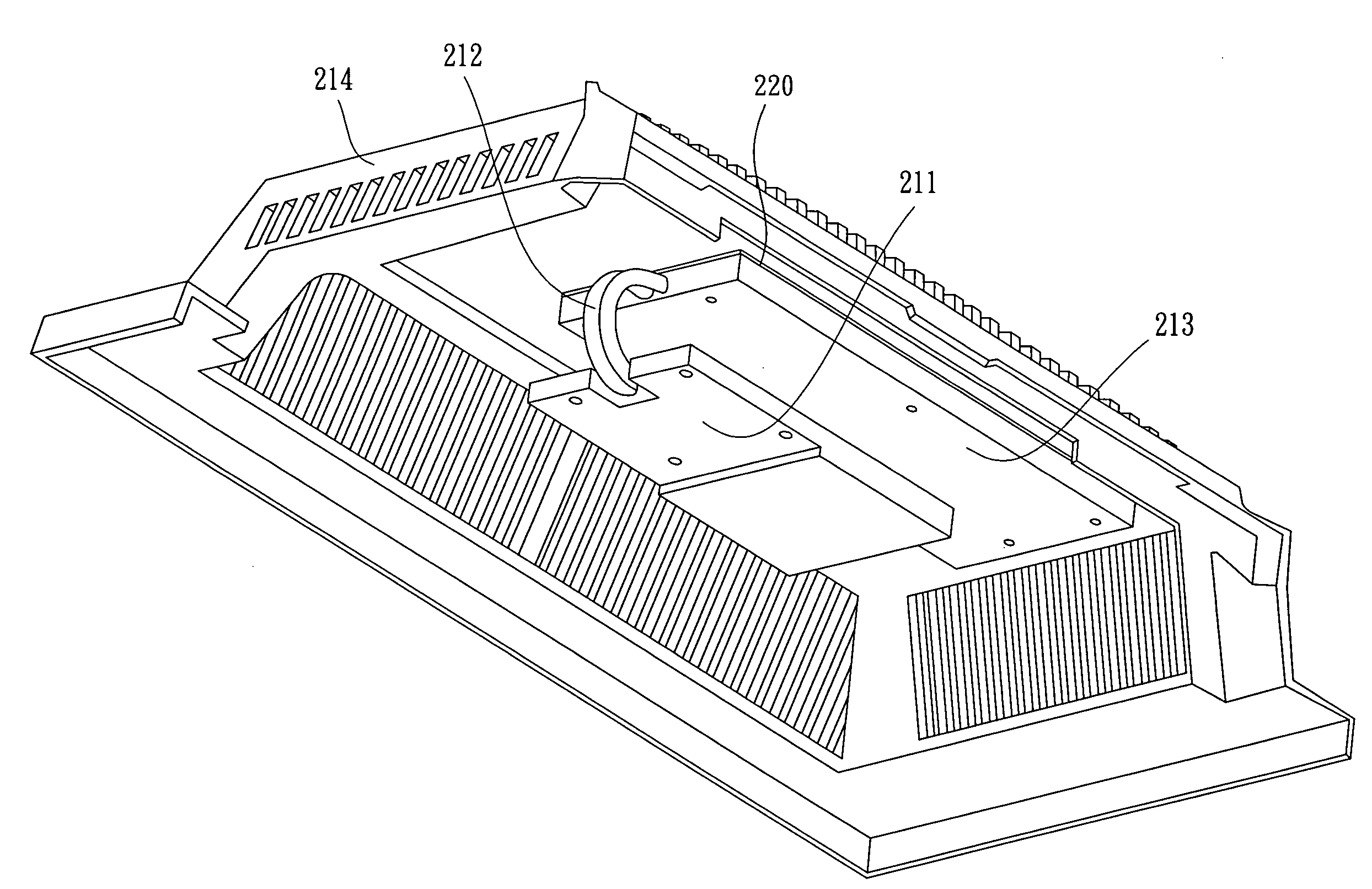
[0010]One objective of this invention is to provide a cooling module without using a cooling fan so that an electronic product incorporating such a cooling module can comply with the noise-free requirements. The cooling module has a first heat conduction plate, a second heat conduction plate and a heat conduction device. The first heat conduction plate is substantially disposed above at least one heat source without coming into contact with each other. The heat conduction device is adapted to connect the first heat conduction plate and the second heat conduction plate, so that heat generated from the at least one heat source is absorbed by the first heat conduction plate and transmitted through the heat conduction device to the second heat conduction plate which is connected to a metal housing. In this way, the heat generated by the at least one heat source is dissipated outwards quickly without using a cooling fan.
[0011]Another objective of this invention is to provide a cooling module for uniformly dissipating heat. The first heat conduction plate is disposed above the at least one heat source without coming into contact with the heat source and has a profile substantially complying with the top of the at least one heat source. Consequently, the heat generated from the at least one heat source is quickly absorbed. Furthermore, in the preferred embodiment, when the second heat conduction plate is provided with an area no less than that of the first heat conduction plate, the heat generated from the at least one heat source can be transmitted, absorbed and then progressively transmitted to the metal housing more quickly. Additionally, since the second heat conduction plate dissipate heat in a uniform way rather than in a single local area, a relatively uniform temperature distribution is obtained on the surface of the metal housing when heat is conducted to the metal housing, thus eliminating the overheating of such the single local area.
[0012]Yet another objective of this invention is to provide a cooling module capable of withstanding a total heat-generating power higher than 5 W. Compared to conventional cooling modules that dissipate heat in a single local area, the multilayered cooling module of this invention distributes heat throughout the metal housing in more uniformly and quickly. As a consequence, the cooling module of this invention is able to withstand a higher total heat-generating power.
[0013]Yet a further objective of this invention is to provide a cooling module that allows for easy maintenance. The second heat conduction plate of this invention is indirectly fixed in the metal housing in a removable manner, while the first heat conduction plate is connected to the second heat conduction plate via the heat conduction device. Therefore, if the metal housing is removed from the electronic product, the electronic components, disposed inside the product, will be exposed immediately to facilitate the maintenance by the maintenance staff.

Problems solved by technology

However, a cooling fan relies on the electric power for operation and usually generates undesired noise during the operation.
It is not suitable for electronic products having requirement for power or noise limitations.
Furthermore, because modern electronic products are becoming increasingly smaller, there may be insufficient space to accommodate a large cooling fan.
Even if some electronic products are free from such limitations, a cooling fan disposed therein often tends to fail after operation for a long period of time.
However, the natural heat dissipation of hot air through the heat dissipating holes usually delivers a poor cooling effect, so another kind of improved heat dissipating module has also been proposed in the prior art.
Therefore, such a cooling module only makes a very limited improvement on the cooling effect, and also tends to dissipate heat unevenly.
In more detail, after a heat-generating component has operated for a period of time, the housing thereof tends to present a non-uniform temperature distribution with a high temperature concentrating in a single local area.
As a result, the temperature at the local area may be higher than 100° C., with a risk of burns or even housing deformation.

Method used


Image

  • Cooling Module
  • Cooling Module
  • Cooling Module

Examples


Embodiment Construction

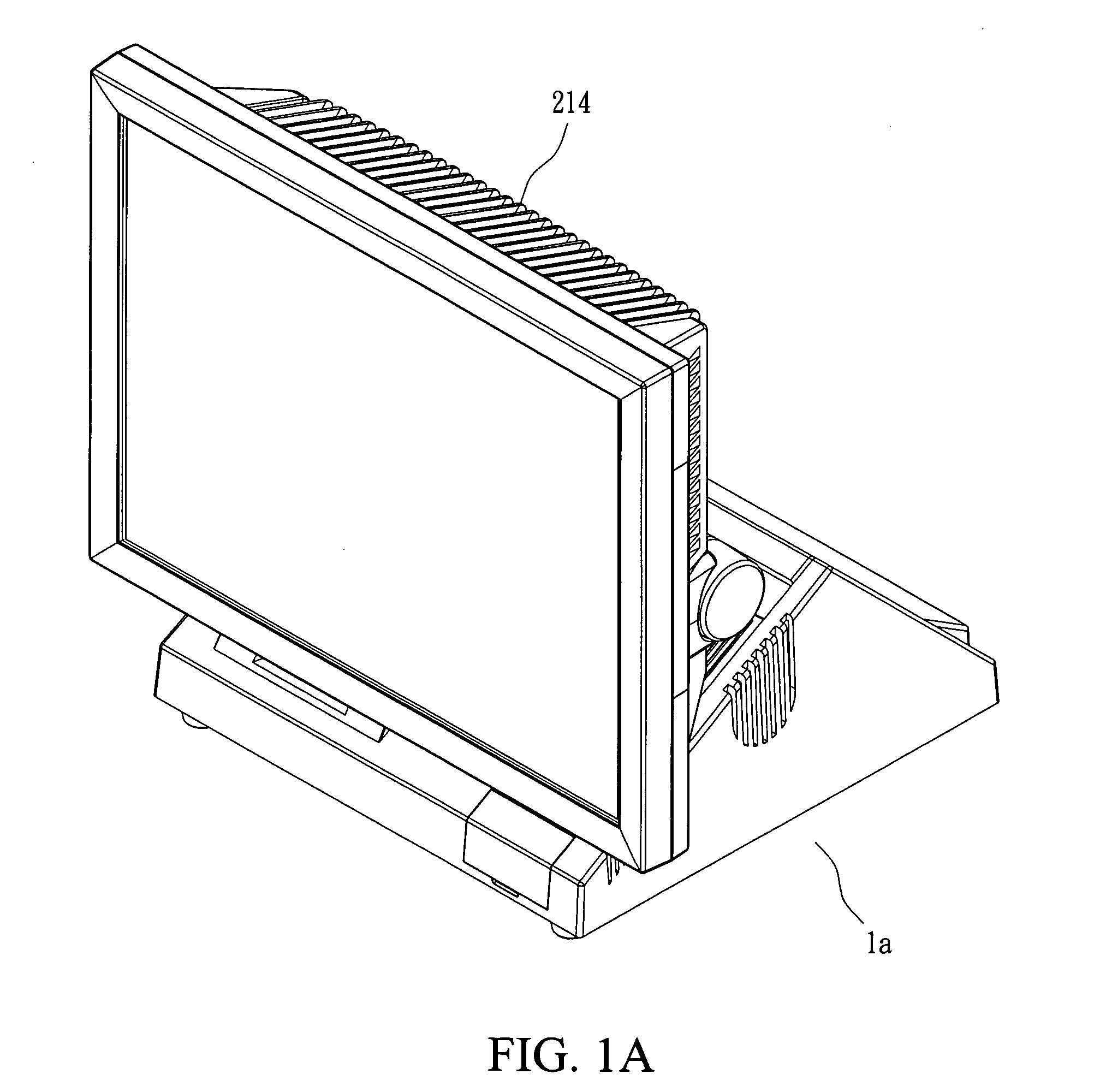
[0022]FIG. 1A illustrates an electronic apparatus, for example, a calculation processing apparatus. More particularly, the calculation processing apparatus is a point of sale (POS) apparatus 1a. One of the features of the POS apparatus 1a is that no cooling fan is used therein so that the noise caused by the fan can be effectively decreased and the maintenance is easy. The following description provides several embodiments of a cooling module of this invention when being used to provide effective heat dissipation in the POS apparatus 1a. However, as may be appreciated by those skilled in the art, the cooling module disclosed in this invention may also be applied to other different electronic apparatuses.

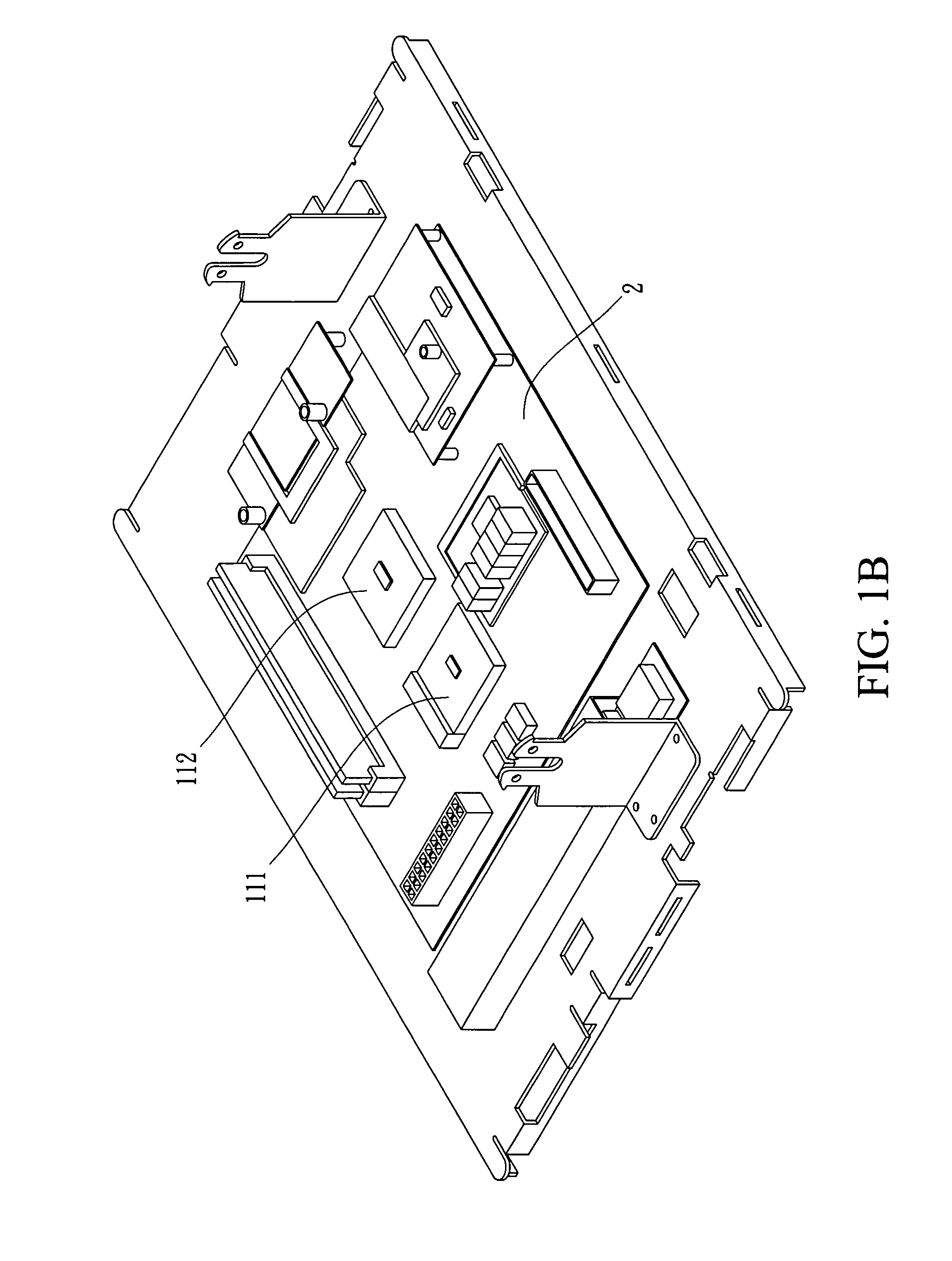
[0023]FIG. 1B depicts a heat-generating block of a circuit board 2 disposed inside the POS apparatus 1a. The block includes at least one electronic component. For instance, there are two electronic components 111, 112, which may be South Bridges, North Bridges, CPUs, memories or the ...


PUM


Abstract

A cooling module for using in a metal housing of a calculation processing apparatus is disclosed. The cooling module is adapted to cool at least one heat source inside the metal housing. The cooling module comprises a first heat conduction plate, a second heat conduction plate and a heat conduction device, wherein the first heat conduction plate covers the heat source, the second heat conduction plate connects to the metal housing, and the heat conduction device is adapted to connect the first heat conduction plate with the second heat conduction plate. After the heat generated by the heat source is absorbed by the first heat conduction plate, the heat is transmitted to the second heat conduction plate through the heat conduction device, and will be dissipated uniformly throughout the metal housing.

Description

[0001]This application claims the benefit from the priority of Taiwan Patent Application No. 096148193 filed on Dec. 17, 2007, the contents of which are herein incorporated by reference in their entirety.CROSS-REFERENCES TO RELATED APPLICATIONS[0002]Not applicable.BACKGROUND OF THE INVENTION[0003]1. Field of the Invention[0004]The present invention provides a cooling module, and particularly, relates to a cooling module for cooling at least one heat source disposed inside a metal housing of a calculation processing apparatus.[0005]2. Descriptions of the Related Art[0006]The advancement of science and technologies has resulted in the widespread use of calculation processing apparatuses in various electronic products, such as personal computers, personal digital assistants (PDAs) or the like. A calculation processing apparatus generally comprises a lot of electronic components that generate heat during the operation, such as a central processing unit (CPU), a memory, or an integrated ...

Claims


Application Information

Patent Timeline
IPC IPC(8): F28D15/02F28F7/00
CPCG06F1/20
Inventor TU, CHIH-SENLIU, TANG-AN
Owner PARTNER TECH
Learn More