Retaining head and contact tip for controlling wire contour and contacting point for gmaw torches

a technology of retaining head and contact tip, which is applied in the direction of welding apparatus, electrode supporting devices, manufacturing tools, etc., can solve the problems of discontinuous beads, cold welding, and arc-low energy consumption, and achieves stable contact force, minimizes the effect of welding wire cast, and straight welding wire contour

Active Publication Date: 2009-06-18
ILLINOIS TOOL WORKS INC
View PDF16 Cites 62 Cited by
  • Summary
  • Abstract
  • Description
  • Claims
  • Application Information

AI Technical Summary

Benefits of technology

[0009]The present invention provides a gooseneck, retaining head and contact tip for controlling wire contour and contacting point for MIG (GMAW) torches. The present invention achieves straight welding wire contour when the welding wire is fed out of the contact tip. The present invention minimizes the effect of welding wire cast and

Problems solved by technology

When a contact tip of a MIG torch is used and deteriorated, the energy transfer efficiency decreases.
This results in lower energy (or voltage) being consumed at the arc.
When the energy consumption is too low to maintain a smooth welding arc, stubbing occurs, which causes defects such as cold welding and discontinuous beads.
However, if the wire cast is too tight, the portion of wire that sticks out of the contact tip, between the contact tip and the arc, is significantly curved, causing misalignment issu

Method used


Image

  • Retaining head and contact tip for controlling wire contour and contacting point for gmaw torches
  • Retaining head and contact tip for controlling wire contour and contacting point for gmaw torches
  • Retaining head and contact tip for controlling wire contour and contacting point for gmaw torches

Examples


first embodiment

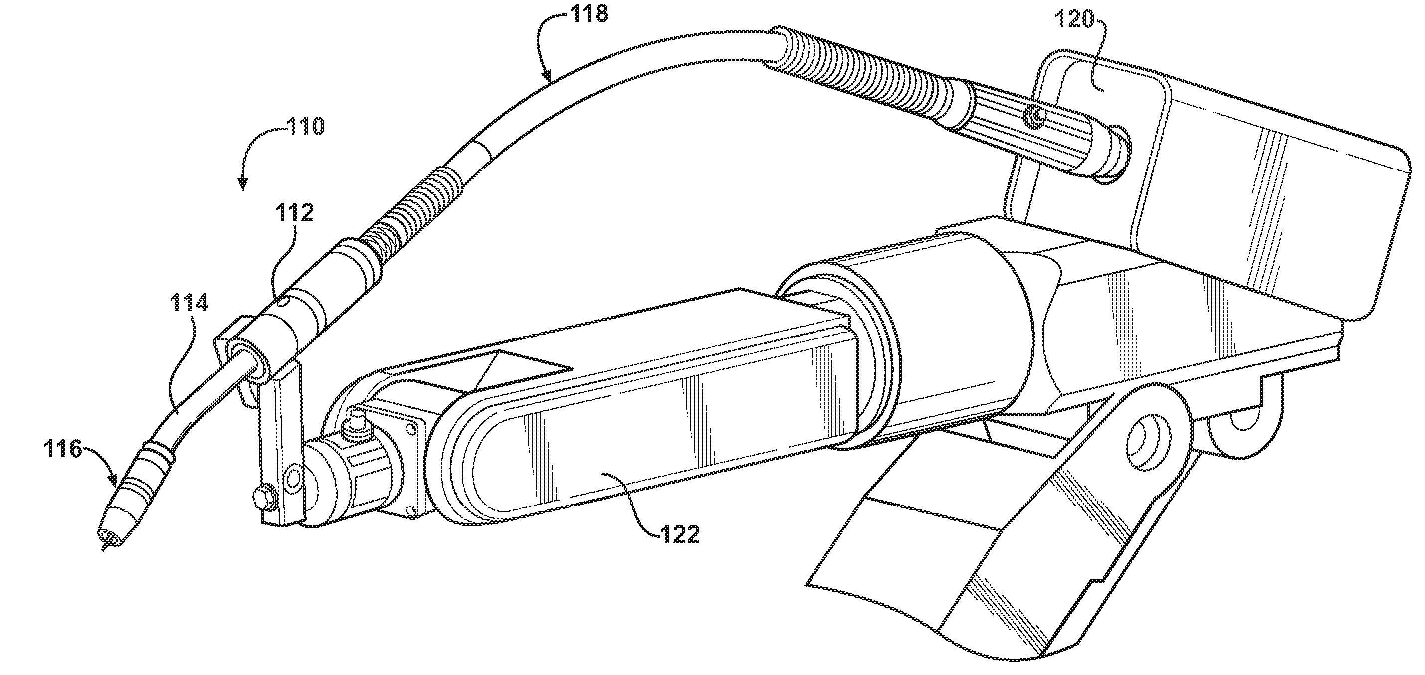
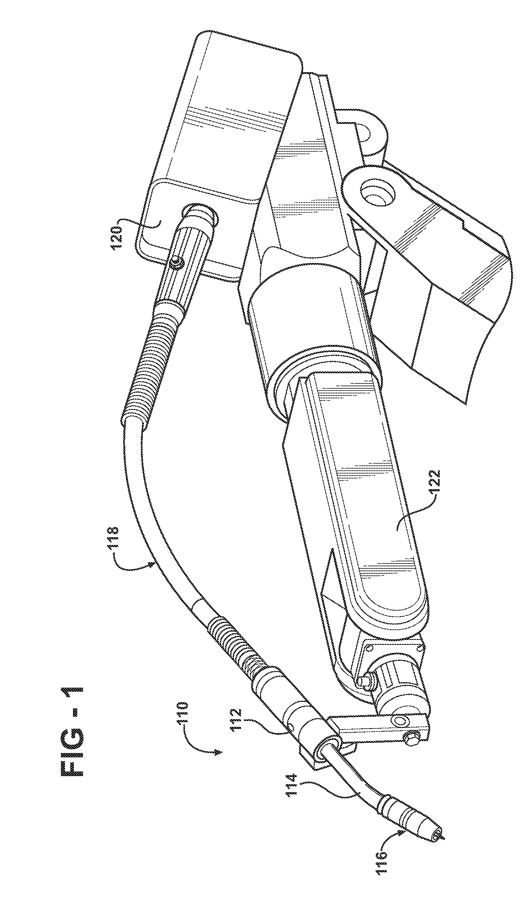
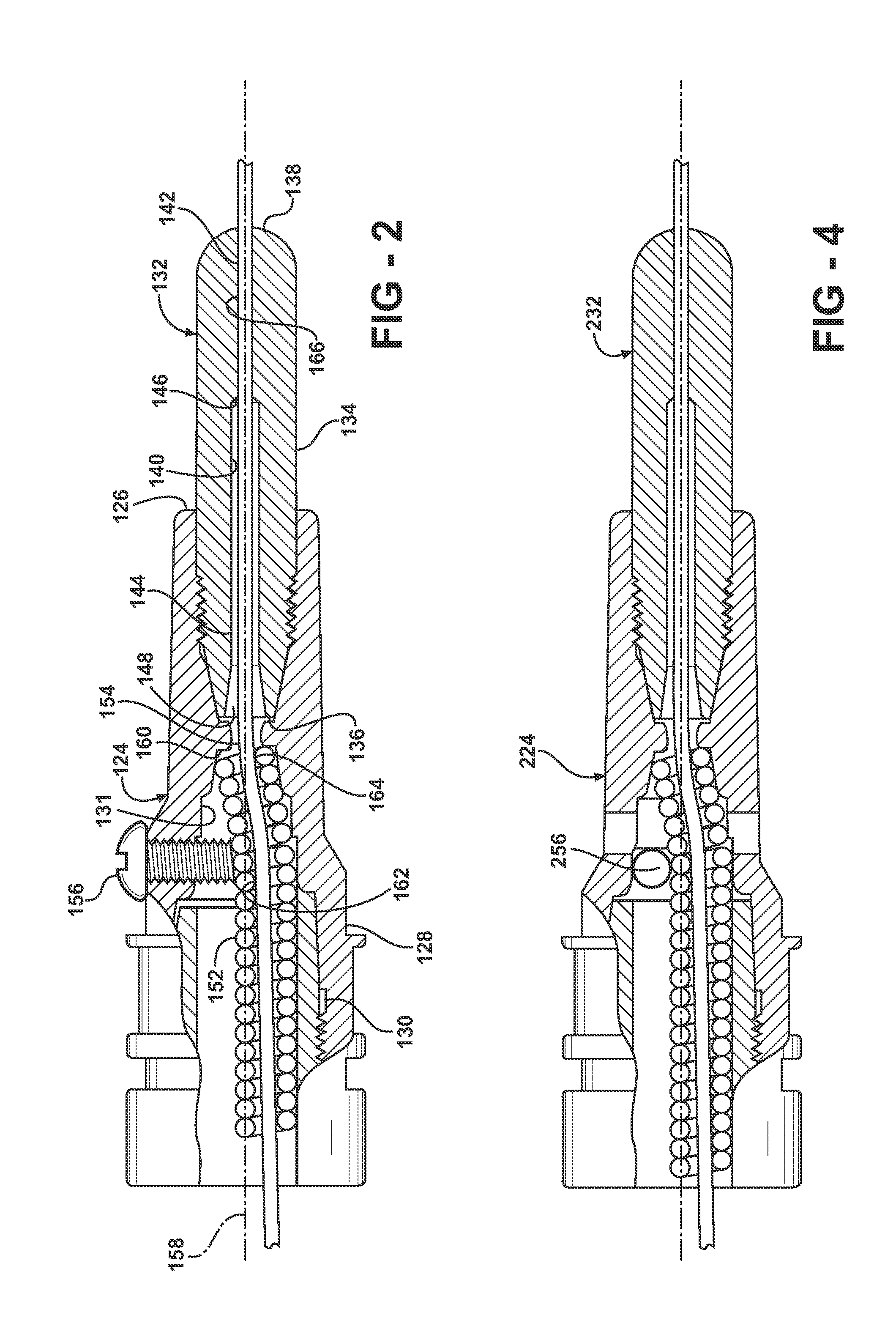
[0030]Turning to FIGS. 1 and 2, in the invention, the front end 116 of the welding torch more specifically includes a retaining head 124 having a front, contact tip mounting end 126 and an opposite, retaining head mounting end 128 at its rear. The contact tip mounting end 126 is adapted to receive and mount a contact tip 132. A throughbore 130 extends axially from the contact tip mounting end 126 to the retaining head mounting end 128. The throughbore 130 includes a stepped or tapered reduced diameter portion 131 in which the diameter of the throughbore gradually decreases in a direction from the retaining head mounting end 128 to the contact tip mounting end 126. The diameter of the throughbore 130 in the reduced diameter portion 131 is smaller than the diameter of the throughbore 130 at the retaining head mounting end 128.

[0031]The contact tip 132 includes a body 134 having a mounting end 136 and an opposite tip end 138. A stepped throughbore 140 extends axially through the body 1...

fourth embodiment

[0042]In a fourth embodiment shown in FIG. 6, the deflector 456 is disposed in the gooseneck 414 rather than the retaining head 424.

fifth embodiment

[0043]In a fifth embodiment shown in FIG. 7, the deflector includes a rear pin 572 and a front pin 574 disposed in the retaining head 524, and correspondingly the liner 552 is recessed behind the rear pin 572. Alternatively, the pins 572, 574 may be rollers. The pins 572, 574 are generally parallel to each other and perpendicular to the centerline 558 of the throughbore 530. The rear and front pins 572, 574 guide the contour of the welding wire 554 by directly contacting the welding wire. The distance between the pins 572, 574 may be approximately 0.5 to 0.8 inches, and the welding wire may be bent at an angle of approximately 4.5 to 6 degrees between the pins, thereby forming an obtuse angle. Optionally, a cylindrical tube 576 may be coaxially inserted into the throughbore 530 of the retaining head 524 and between the rear and front pins 572, 574. The tube 576 prevents welding spatter that comes through gas holes 578 from passing into the inlet 548 of the contact tip 532.


PUM

PropertyMeasurementUnit
Lengthaaaaaaaaaa
Angleaaaaaaaaaa
Diameteraaaaaaaaaa

Abstract

A retaining head for a MIG welding device includes a contact tip mounting end, an opposite retaining head mounting end, and a throughbore extending from one of the ends to the other end. A deflector is disposed along the throughbore and is adjustable for imparting a bend in welding wire passing through the throughbore. The deflector provides a straight wire contour for the welding wire that is fed out of the welding torch, while maintaining sufficient contact force between the welding wire and the contact tip. The deflector also reduces the effect of wire twist on the contact point between the welding wire and the contact tip.

Description

CROSS REFERENCE TO RELATED APPLICATION[0001]This application claims the priority of U.S. Provisional Application No. 61 / 014,470 filed Dec. 18, 2007.TECHNICAL FIELD[0002]This invention relates to goosenecks, retaining heads and contact tips of MIG (GMAW) guns or torches that are configured to bend welding (electrode) wire, thereby achieving straight contour of the welding wire when it is fed out of the contact tip and improving the contact between the welding wire and the contact tip.BACKGROUND OF THE INVENTION[0003]A common metal welding technique employs the heat generated by electrical arcing to transition a portion of a workpiece to a molten state, and the addition of filler metal from a welding wire. One technique that employs this arcing principle is wire-feed welding. Wire-feed welding involves routing welding current from a power source into an electrode that is brought into close proximity or contact with the workpiece. In typical wire-feed systems, electrode welding wire is...

Claims


Application Information

Patent Timeline
IPC IPC(8): B23K9/173B23K9/28
CPCB23K9/295B23K9/123
Inventor MA, TIEJUNPINSONNEAULT, PAUL-DAVIDJAEGER, THOMAS
Owner ILLINOIS TOOL WORKS INC
Why Eureka
Try Eureka