Nacelle inlet thermal Anti-icing spray duct support system

a technology of anti-icing spray and nacelle inlet, which is applied in the direction of power plant arrangement/mounting, de-icing equipment, aircraft power plants, etc., can solve the problems of prone to accumulation of ice, and achieve the effect of effectively accommodating thermal expansion and contraction of components

Active Publication Date: 2009-06-18
SPIRIT AEROSYSTEMS
View PDF23 Cites 47 Cited by
  • Summary
  • Abstract
  • Description
  • Claims
  • Application Information

AI Technical Summary

Benefits of technology

[0005]The present invention solves the above-described problems and provides a distinct advance in the art of aircraft anti-icing systems. More particularly, the present invention provides an anti-icing system for a leading edge of an aircraft which more effectively accommodates thermal expansions and contractions of components of the anti-icing system.

Problems solved by technology

Because the inlet section is forward of the engine and therefore not heated directly by the engine, it is prone to the accumulation of ice.

Method used


Image

  • Nacelle inlet thermal Anti-icing spray duct support system
  • Nacelle inlet thermal Anti-icing spray duct support system
  • Nacelle inlet thermal Anti-icing spray duct support system

Examples


Embodiment Construction

[0025]The following detailed description of the invention references the accompanying drawings that illustrate specific embodiments in which the invention can be practiced. The embodiments are intended to describe aspects of the invention in sufficient detail to enable those skilled in the art to practice the invention. Other embodiments can be utilized and changes can be made without departing from the scope of the present invention. The following detailed description is, therefore, not to be taken in a limiting sense. The scope of the present invention is defined only by the appended claims, along with the full scope of equivalents to which such claims are entitled.

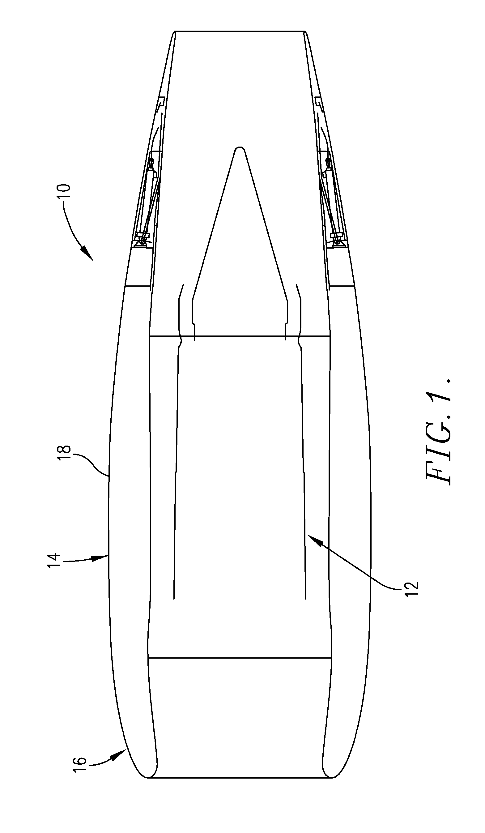
[0026]Turning now to the drawing figures, and particularly FIG. 1, an aircraft engine assembly 10 in which embodiments of the anti-icing system of the present invention may be used is illustrated. The aircraft engine assembly 10 is configured for attachment below a wing of an aircraft such as the Boeing 737 or 747 and b...


PUM


Abstract

An anti-icing system for an aircraft engine nacelle comprises a generally ring-shaped hollow spray tube for directing hot gasses toward a portion of the nacelle; a plurality of fasteners for attaching the spray tube to a support structure of the aircraft engine; and a supply duct for delivering the hot gasses from the aircraft engine to the spray tube. The spray tube includes two closed ends which define a thermal expansion gap therebetween to accommodate thermal expansions and contractions caused by the hot gasses. Each of the fasteners comprises a support bracket for attachment to the support structure of the aircraft and a guide assembly for supporting the spray tube to the support bracket. The guide assembly includes a generally ring-shaped block for encircling the spray tube, a bushing positioned within the block for contact with a bearing sleeve of the spray tube, and a pair of bushing retainers positioned on opposite sides of the block for retaining the bushing within the block. The bushings permit the spray tube to slip relative to the fasteners to further accommodate thermal expansions and contractions.

Description

BACKGROUND OF THE INVENTION[0001]1. Field of the Invention[0002]The present invention relates to aircraft engine assemblies. More particularly, the invention relates to an anti-icing system for a nacelle inlet of an aircraft engine assembly.[0003]2. Description of the Prior Art[0004]Anti-icing systems are commonly used for preventing ice from accumulating on the leading edges of aircraft structures such as engine inlets and wings. One prior art anti-icing system includes a piccolo-type spray tube which directs hot gasses from an aircraft's engine toward an area to be de-iced. One problem with these types of systems is that the spray tube is alternatively subjected to ambient temperatures when the aircraft is not in use and extremely high temperatures when hot gasses are passed therethrough, resulting in cyclic thermal expansions and contractions of the tube. Such expansions and contractions can damage the tube itself and the brackets or other supports which attach the tube to the ai...

Claims


Application Information

Patent Timeline
Patent Type & Authority Applications(United States)
IPC IPC(8): B64D15/02
CPCB64D33/02B64D2033/0286B64D2033/0233
Inventor STERNBERGER, JOE E.
Owner SPIRIT AEROSYSTEMS
Why Eureka
Try Eureka