Dynamo-electrical machine with tooth-wound coils

a dynamo-electrical machine and coil technology, applied in the field of dynamo-electrical machines, can solve the problems of reducing affecting the efficiency of the rotor, and requiring a large amount of effort, and achieve the effect of increasing the copper filling factor in the slo

Inactive Publication Date: 2009-06-18
SIEMENS AG
View PDF2 Cites 20 Cited by
  • Summary
  • Abstract
  • Description
  • Claims
  • Application Information

AI Technical Summary

Benefits of technology

[0013]The insertion process may be carried out, for example, by means of snap-action connections or by pushing axially into the slot. This additionally presses the conductors of the winding together, thus also increasing the copper filling factor in the slot.

Problems solved by technology

In particular, the widened tooth heads make it harder, however, to introduce the winding using known processes such as pulling-in technique, or by means of needle winders, into the stator slots which are located between the teeth, and in the end this results in a comparatively low copper filling level, involving a large amount of effort, in the slots.
Although this would in better copper filling, the flux guidance across the air gap to the rotor becomes inadequate.
The use of slot seals composed of plastic with a predeterminable permeability have been proposed but the outcome was unsatisfactory.

Method used


Image

  • Dynamo-electrical machine with tooth-wound coils
  • Dynamo-electrical machine with tooth-wound coils
  • Dynamo-electrical machine with tooth-wound coils

Examples


Embodiment Construction

[0025]Throughout all the figures, same or corresponding elements may generally be indicated by same reference numerals. These depicted embodiments are to be understood as illustrative of the invention and not as limiting in any way. It should also be understood that the figures are not necessarily to scale and that the embodiments are sometimes illustrated by graphic symbols, phantom lines, diagrammatic representations and fragmentary views. In certain instances, details which are not necessary for an understanding of the present invention or which render other details difficult to perceive may have been omitted.

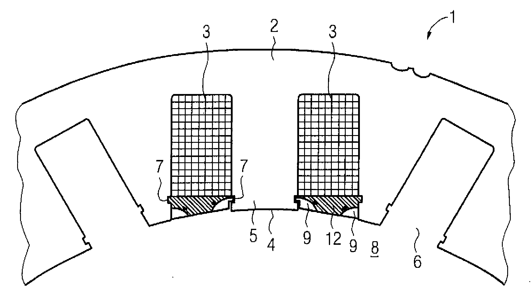
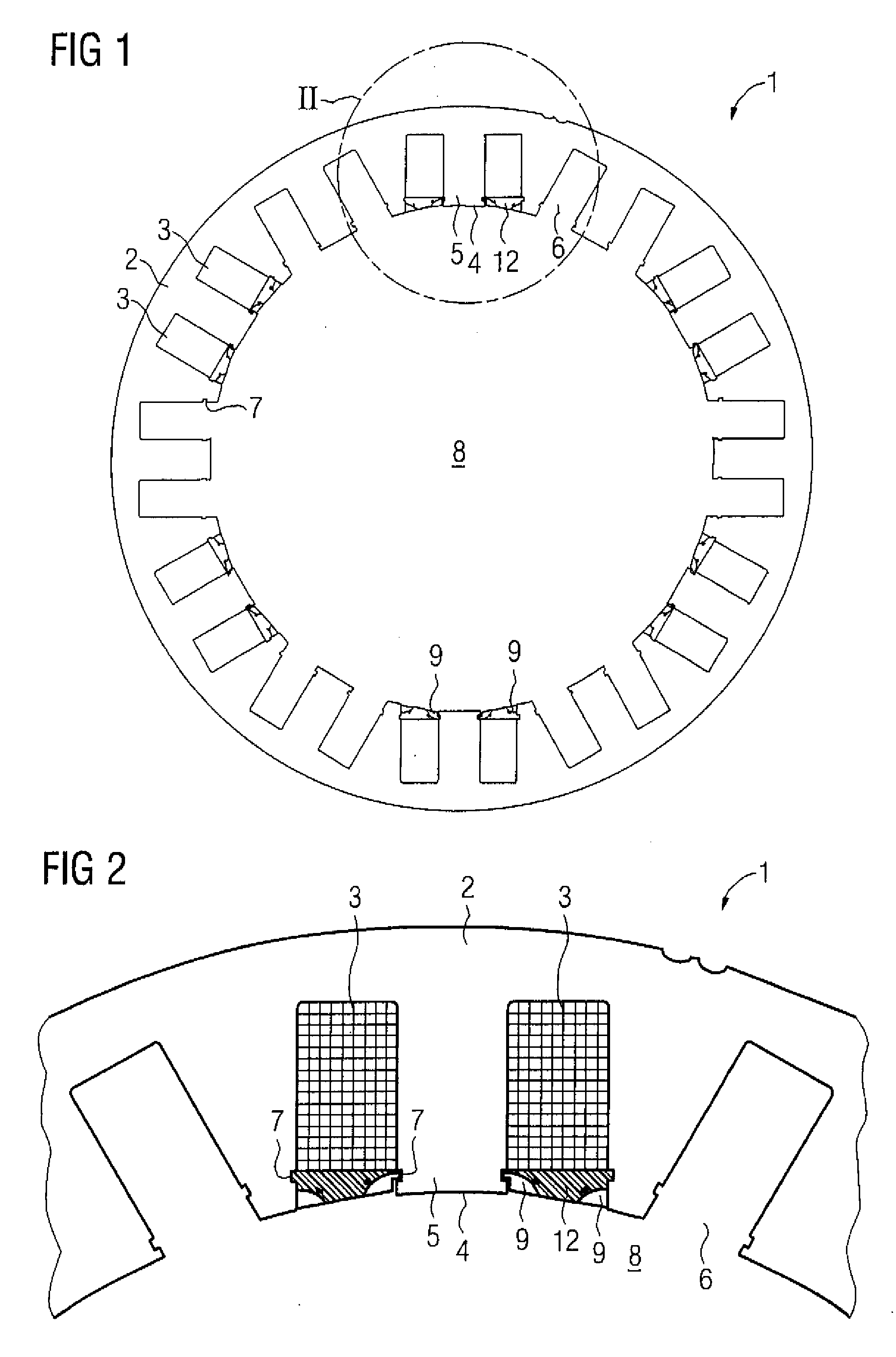
[0026]Turning now to the drawing, and in particular to FIG. 1, there is shown a schematic illustration of a laminated stator core, generally designated by reference numeral 1 and made of laminates 2, of which only one is shown here. The laminate 2 has various tooth shapes, wherein a tooth with a tooth shank 5 and a tooth head 4 of the same width are each surrounded by a toot...


PUM


Abstract

A dynamo-electrical machine includes a stator with teeth which are aligned with respect to a rotor, wherein at least a predeterminable number of teeth are surrounded by a winding system which is arranged in slots. The slots which are formed by the teeth and designed to be open, are each closed by a slot sealing element which has an electrically non-conductive and magnetically non-permeable material in which a tooth head widening element is provided in the area of those tooth sections of the tooth heads which face the air gap.

Description

CROSS-REFERENCES TO RELATED APPLICATIONS[0001]This application claims the priority of European Patent Application, Serial No. 07024228, filed Dec. 13, 2007, pursuant to 35 U.S.C. 119(a)-(d), the content of which is incorporated herein by reference in its entirety as if fully set forth herein.BACKGROUND OF THE INVENTION[0002]The present invention relates, in general, to a dynamo-electrical machine.[0003]Teeth of stators of dynamo-electrical machines normally have tooth heads which, in particular, are wider than a tooth shank. They are used to make the magnetic flux in the air gap of the dynamo-electrical machine uniform, and this has an advantageous effect on the characteristic data and function of the dynamo-electrical machines. In particular, the widened tooth heads make it harder, however, to introduce the winding using known processes such as pulling-in technique, or by means of needle winders, into the stator slots which are located between the teeth, and in the end this results...

Claims


Application Information

Patent Timeline
Patent Type & Authority Applications(United States)
IPC IPC(8): H02K3/493
CPCH02K3/493
Inventor BOTT, ERICHVOLLMER, ROLF
Owner SIEMENS AG
Why Eureka
Try Eureka