Time to digital converter with error protection

a time to digital converter and error protection technology, applied in the field of time to digital converters, can solve problems such as the difficulty of improving the estimation resolution of conventional tdcs

Inactive Publication Date: 2009-06-18
MEDIATEK INC
View PDF2 Cites 19 Cited by
  • Summary
  • Abstract
  • Description
  • Claims
  • Application Information

AI Technical Summary

Benefits of technology

[0008]The invention discloses time to digital converters. According to one embodiment, the time to digital converter comprises a first time to digital converting module, a selection and time-amplifying module, a second time to digital converting module and a decoder. The first time to digital converting module delays a first signal to generate a plurality of delayed first signals, and reads out the states of the delayed first signals according to a second signal. The read-out states form first digital data. The selection and time-amplifying module determines the first zero bit of the first digital data and then selects and stretches the corresponding delayed first signal. The stretched result is outputted by the selection and time-amplifying module as a first reference signal. In additional to outputting the first reference signal, the selection and time-amplifying module further stretches the second signal along the time axis and outputs the stretched second signal. The second time to digital converting module delays the stretched second signal to generate a plurality of delayed and stretched second signals, and reads out the states of the delayed and stretched second signals according to the first reference signal to generate second digital data. The first and second digital data are sent to the decoder to be decoded for estimating a time difference between the first and second signals.

Problems solved by technology

Since the value of the unit delay time T is mainly dependent on the manufacturing process of the delay units DU1˜DU4, it is difficult to improve the estimation resolution of the conventional TDCs.

Method used


Image

  • Time to digital converter with error protection
  • Time to digital converter with error protection
  • Time to digital converter with error protection

Examples


Embodiment Construction

[0019]The following description shows the embodiments of carrying out the invention. This description is made for the purpose of illustrating the general principles of the invention and should not be taken in a limiting sense. The scope of the invention is best determined by reference to the appended claims.

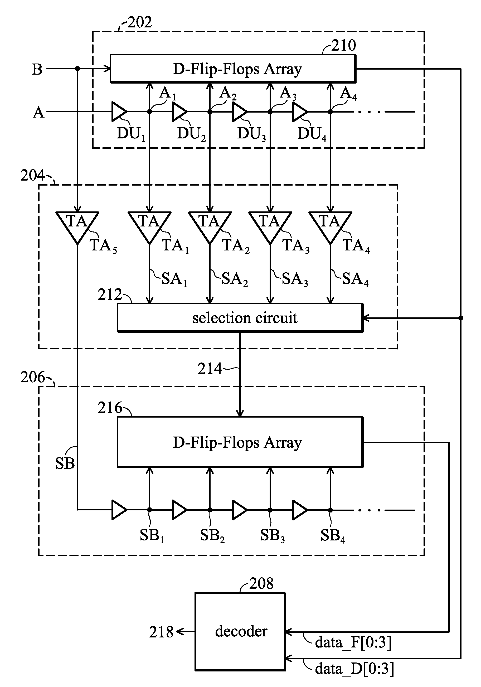
[0020]FIG. 2A illustrates an embodiment of the time to digital converter of the invention, which estimates a time difference between a first signal A and a second signal B. The time to digital converter comprises a first time to digital converting module 202, a selection and time-amplifying module 204, a second time to digital converting module 206 and a decoder 208. In this embodiment, the first time to digital converting module 202 comprises a plurality of delay units DU1˜DU4 and a D-Flip-Flops array 210. The delay units DU1˜DU4 are coupled in series to delay the first signal A to generate a plurality of delayed first signals A1˜A4. The D-Flip-Flops array 210 is triggered by th...


PUM


Abstract

Time to digital converters (TDCs) with high resolution are disclosed. The TDC includes a first time to digital converting module, a selection and time amplifying module, a second time to digital converting module and a decoder, and is applied in estimating a time difference between a first signal and a second signal. As the delay time of the delay units of the time to digital converting modules is the unit of the time difference measurement, the first and second time to digital converting modules are responsible for the integral portion and the fractional portion of the estimated time difference, respectively. Moreover, by introducing the normalization process, the linearity of the converting characteristic of the TDC can be improved; by adding an error detection circuit to the TDC, the possible metastable problem can be prevented.

Description

CROSS REFERENCE TO RELATED APPLICATIONS[0001]This application is related to co-pending U.S. utility application Ser. No. 12 / 235,624, filed on Sep. 23, 2008, entitled “Error Protection Method, TDC module, CTDC Module, All-Digital Phase-Locked Loop, and Calibration Method thereof” and claiming the priority of U.S. Provisional Applications No. 60 / 980,172 filed on Oct. 16, 2007 and 60 / 980,461 filed on Oct. 17, 2007, the entirety of which is incorporated herein by reference.BACKGROUND OF THE INVENTION[0002]1. Field of the Invention[0003]The present invention relates to time to digital converters (TDCs), and in particular relates to high resolution TDCs.[0004]2. Description of the Related Art[0005]FIG. 1A illustrates a conventional time to digital converter (TDC), which estimates the time difference between a first signal A and a second signal B. The conventional TDC comprises a time to digital converting module 102 and a decoder 104. The time to digital converting module 102 comprises a ...

Claims


Application Information

Patent Timeline
Patent Type & Authority Applications(United States)
IPC IPC(8): H03M5/08
CPCH03L7/085H03L2207/50H03L7/0991
Inventor CHANG, HSIANG-HUI
Owner MEDIATEK INC
Why Eureka
Try Eureka