
Obstacle detecting control device of vehicle

Inactive Publication Date: 2009-06-18
MAZDA MOTOR CORP
View PDF32 Cites 4 Cited by
  • Summary
  • Abstract
  • Description
  • Claims
  • Application Information

AI Technical Summary

Benefits of technology

[0006]The present invention has been devised in view of the above-described problem, and an object of the present invention is to provide an obstacle detecting control device of a vehicle that can detect any obstacle promptly and surely regardless of where it is present, thereby properly controlling any operational device.
[0013]Thereby, the transmission-term ratio of the radar waves transmitted to the specified transmission area that may be appropriate to the current vehicle traveling speed can be made large, so that any obstacle in that area can be detected promptly and surely. Specifically, it is preferable that the control device be configured to control the radar-waves transmitting portion so that the transmission-term ratio of the radar waves transmitted to the plural transmission areas is changeable in accordance with the vehicle starveling speed detected by the traveling-speed detecting device in such a manner that the transmission-term ratio of the radar waves transmitted to the near transmission area becomes large compared with that to the far transmission area when the vehicle traveling speed is relatively slow.
[0015]Thereby, the transmission-term ratio of the radar waves transmitted to the specified transmission area that may be appropriate to the current width of the road on the vehicle travels can be made large, so that any obstacle in that area can be detected promptly and surely. Specifically, it is preferable that the control device be configured to control the radar-waves transmitting portion so that the transmission-term ratio of the radar waves transmitted to the plural transmission areas is changeable in accordance with the road width detected by the road-width detecting device in such a manner that the transmission-term ratio of the radar waves transmitted to the near transmission area becomes large compared with that to the far transmission area when the road width is relatively narrow. Thus, since the possibility of obstacle's rapid emergence in the near area is higher in case the vehicle traveling on the relatively narrow road, such obstacle can be detected promptly and surely with the above-described setting of the transmission-term ratio of the radar waves.
[0017]Specifically, it is preferable that the control device be configured to control the radar-waves transmitting portion so that the transmission-term ratio of the radar waves transmitted to the plural transmission areas is changeable in accordance with the pedestrian detected by the pedestrian detecting device in such a manner that the transmission-term ratio of the radar waves transmitted to a specified transmission area that corresponds to a location where the detected pedestrian is present is larger than that to other transmission area. Further, in case it is detected that plural pedestrians are present in the plural areas of the transmission areas, the transmission-term ratios of the millimeter waves transmitted to the respective transmission areas may be changed in accordance with the number ratio of present pedestrians. Thereby, since the transmission-term ratio of the radar waves transmitted to the specified transmission area that may have higher possibility of the detected pedestrian coming in is made properly large, such pedestrian (obstacle) can be detected promptly and surely.

Problems solved by technology

However, the above-described selection control may be insufficient.
For example, when the vehicle is traveling at the high speed with the far transmission area selected, another obstacle could possibly emerge rapidly in the near transmission area.
In this case, since the radar waves are transmitted only to the far transmission area, there is a concern that the detection of any obstacle emerging in the near transmission area would be delayed improperly.

Method used


Image

  • Obstacle detecting control device of vehicle
  • Obstacle detecting control device of vehicle
  • Obstacle detecting control device of vehicle

Examples


embodiment 1

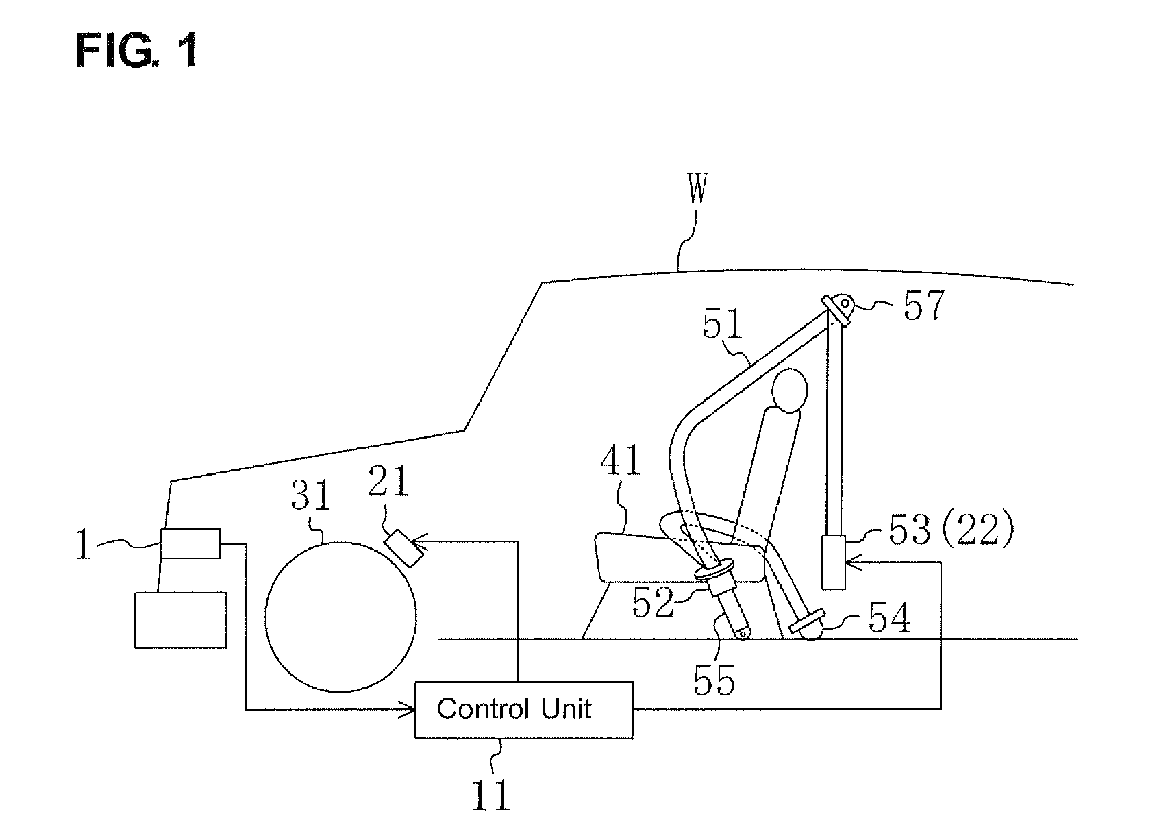
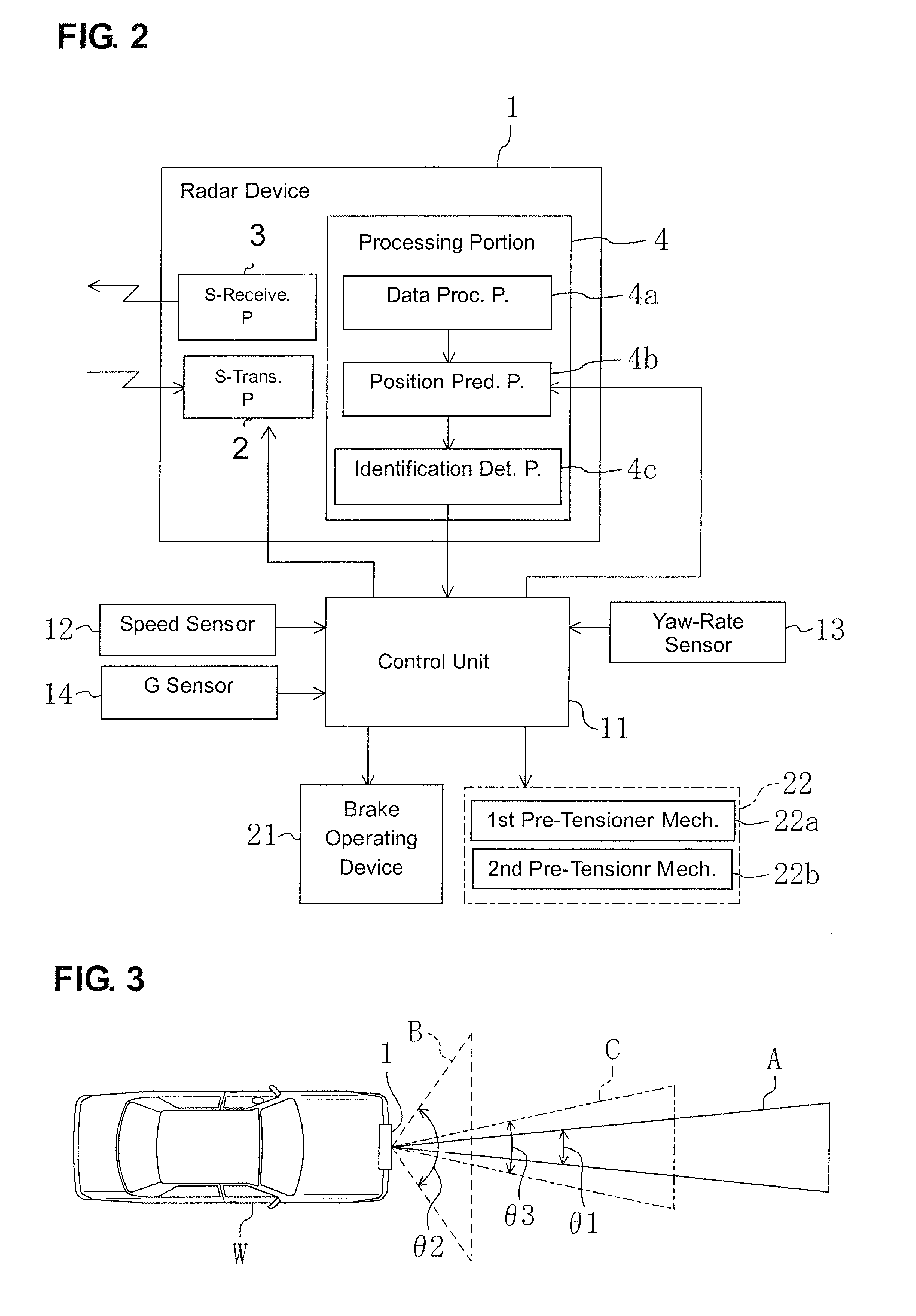
[0030]FIG. 1 shows a vehicle W (a traveling vehicle as an automotive vehicle in the present embodiment) that is equipped with an obstacle detecting control device according to a first embodiment of the present invention. A radar device 1, as an obstacle detecting device, operative to detect an obstacle that may exist in front of the vehicle W is provided at a front end portion of the vehicle W. The radar device 1 is an electronic scanning type of millimeter-wave radar device, which comprises, as shown in FIG. 2, a signal-transmitting portion 2, as a radar-waves transmitting portion, which transmits millimeter waves (radar waves) forward, scanning a specified-angled area in a substantially horizontal direction, a signal-receiving portion 3, as a radar-waves receiving portion, which receives millimeter waves reflected on any obstacle in front of the vehicle W, and a processing portion 4 that performs the following obstacle-detection processing based on data received by the signal-rece...

embodiment 2

[0054]FIG. 7 shows a second embodiment of the present invention, which comprises a GPS sensor 15 to detect a present location of the vehicle W and a DVD-ROM 16 to store information of road map (including the road width) in addition to the first embodiment 1. The other hardware structures are the same as those of the first embodiment, whose description is omitted here. Herein, the GPS sensor 15 and the DVD-ROM 16 are part of a navigation device 17, a control portion of which performs the navigation function based on the current location information of the vehicle W detected by the GPS sensor 15 and the road map information stored in the DVD-ROM 16.

[0055]In the present embodiment, a control unit 11′ receives information from the GPS sensor 15 and the DVD-ROM sensor 16, and detects the width of the road on which the vehicle W travels at this moment based on the information. And, it changes the transmission-term ratio of the millimeter waves transmitted to the respective transmission ar...

embodiment 3

[0061]FIG. 9 shows a third embodiment of the present invention, which comprises a CCD camera 19 to take images in front of the vehicle W in addition to the first embodiment 1. The other hardware structures are the same as those of the first embodiment, whose description is omitted here.

[0062]Image data from the CCD camera 19 is inputted to the control unit 11″, and the control unit 11″ detects any pedestrian that is present on the road on which the vehicle W travels outside the transmission areas A, B, C (such as, on a side walk or an edge of the road) and the distance from the vehicle W to the pedestrian. Thus, the pedestrian, specifically, existence of the pedestrian and the distance to the pedestrian are detected as the road condition of the traveling vehicle W. The existence of the pedestrian may be determined based taken images compared with a human's contour, and the distance between the pedestrian and the vehicle W may be determined based on a pedestrian's vertical position i...


PUM


Abstract

A control device controls operational devices based on obstacle-detection state detected by the radar device and controls a radar-waves transmitting portion of the obstacle detecting device based on detection of a vehicle speed sensor. The control device is configured to control the radar-waves transmitting portion so that a ratio of transmission term of radar waves transmitted to plural transmission areas is changeable in accordance with detection of the vehicle speed. Accordingly, any obstacle present in any transmission area can be detected promptly and surely.

Description

BACKGROUND OF THE INVENTION[0001]The present invention relates to an obstacle detecting control device of a vehicle that comprises an obstacle detecting device to detect an obstacle in front of the vehicle.[0002]Conventionally, a radar device, which detects an obstacle by transmitting radar waves forward and then receiving radar waves reflected on the obstacle, is well known. Some type of such radar device can change a detection area, which is disclosed in Japanese Patent Laid-Open Publication No. 7-129900, for example.[0003]An electronic scanning type of radar device has been recently developed. In this radar device the detectable distance is changeable by changing the scanning angle of radar waves transmitted, so that the radar waves can be transmitted to plural transmission areas selectively. That is, the plural transmission areas of radar waves have different values of a distance between its vehicle-presence position and its front tip position. Thus, by changing the scanning ang...

Claims


Application Information

Patent Timeline
IPC IPC(8): G01S13/93G01S13/931
CPCG01S13/42G01S13/931G01S2013/9375G01S2013/9353G01S2013/9357G01S2013/9346G01S2013/9322G01S2013/93185G01S2013/93271G01S2013/932
Inventor IKEDA, KENICHI
Owner MAZDA MOTOR CORP
Learn More