
Control system and method

Active Publication Date: 2008-05-06
FURUNO ELECTRIC CO LTD
View PDF17 Cites 2 Cited by
  • Summary
  • Abstract
  • Description
  • Claims
  • Application Information

AI Technical Summary

Benefits of technology

[0005]The present invention is intended to overcome the aforementioned problem of the prior art. Accordingly, it is an object of the present invention to provide a control system and a control method which make it possible to properly control a subject to be controlled according to a current situation thereof whether the controlled subject is in an oscillating state caused by cyclically occurring external disturbances or in an oscillating state caused by ordinary control operation regardless of the type of the controlled subject and the nature of the disturbances.
[0006]It is another object of the present invention to provide a control state judgment device and a control state judgment method which make it possible to properly distinguish between an oscillating state caused by cyclically occurring external disturbances and an oscillating state caused by ordinary control operation regardless of the type of a subject to be controlled and the nature of the disturbances.

Problems solved by technology

In the presence of such oscillation, it is difficult to distinguish between the oscillation caused by the disturbances and ordinary oscillation caused by the feedback control operation.
In a process of controlling the heading of a ship, for example, it is difficult to distinguish between an oscillating state caused by feedback control operation and an oscillating state caused by the influence of such external disturbances as cyclical rises and falls of ocean waves.
Although it might be possible to distinguish between two kinds of oscillation based on whether the amplitude of periodic changes in the controlled quantity exceeds a preset threshold or not, the value of the threshold to be preset greatly varies with the type and nature of the controlled subject and seriousness of disturbances, so that this threshold approach imposes a great deal of difficulty in designing a control system.

Method used


Image

  • Control system and method
  • Control system and method
  • Control system and method

Examples


Embodiment Construction

[0031]The invention is now described in detail, by way of example, with reference to a preferred embodiment thereof illustrated in the accompanying drawings.

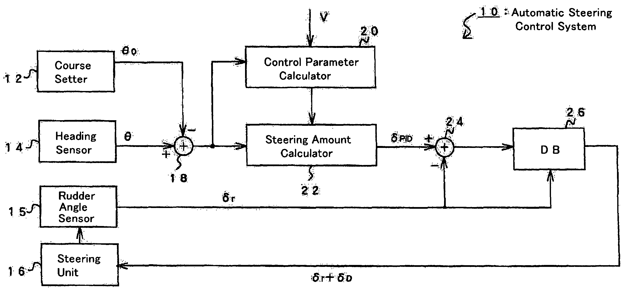
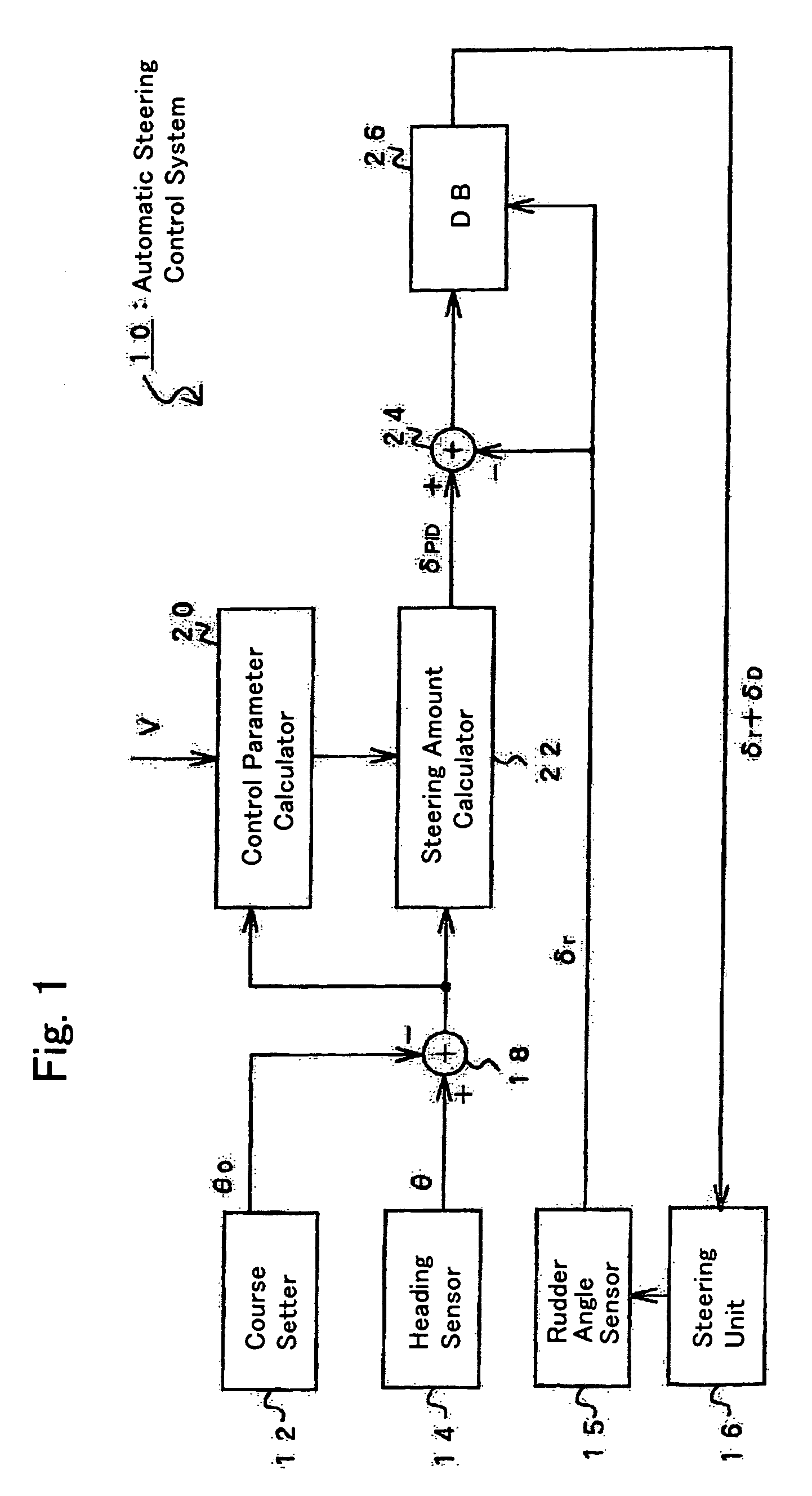
[0032]FIG. 1 is a block diagram showing the configuration of an automatic steering control system 10 according to the preferred embodiment of the invention. Installed on a ship (subject to be controlled), the automatic steering control system 10 includes a course setter 12, a heading sensor 14, a rudder angle sensor 15, a steering unit 16, adders 18, 24, a control parameter calculator 20, a steering amount calculator 22 and a deadband processor 26 as shown in FIG. 1. The automatic steering control system 10 controls the heading of the ship by automatically operating the steering unit 16.

[0033]The course setter 12 outputs information on an intended course θ0 (target value) of the ship. The intended course θ0 may be manually set by a course setting knob or given through mathematical operation by conventional navigation equipment o...


PUM


Abstract

A control system of the invention for regulating a quantity to be controlled based on a deviation of the controlled quantity from a target value thereof and control parameters includes a behavior feature value calculator, a basic state judgment data calculator and a control parameter setter. The behavior feature value calculator detects the period or frequency of behaviors of a specific kind performed by a subject to be controlled. The basic state judgment data calculator calculates the amount of variations in the aforementioned period or frequency. The control parameter setter updates the value of at least one of the control parameters based on the amount of the aforementioned variations.

Description

[0001]This Nonprovisional application claims priority under 35 U.S.C. § 119(a) on Patent Application No(s). 2003-097320 filed in Japan on Mar. 31, 2003, the entire contents of which are hereby incorporated by reference.BACKGROUND OF THE INVENTION[0002]The present invention relates generally to a control system and a control method as well as to a control state judgment device and a control state judgment method. More particularly, the invention pertains to a system and a method which can offer an increased accuracy in detecting an oscillating state in feedback control operation.[0003]A situation occasionally experienced in feedback control operation is oscillation of a controlled system, or subject, in which a deviation of a quantity to be controlled from a target value thereof cyclically increases and decreases in a regular pattern. It is desirable to instantly detect such an oscillating state and vary appropriate control parameters in a manner suitable for the situation.[0004]When...

Claims


Application Information

Patent Timeline
IPC IPC(8): B60L3/00B60L15/00G05D1/00G05D3/00B63H25/04G05B11/01G05B13/02G05D1/02G06F17/00
CPCG05B13/0275G05B11/01G05D1/02G05D1/0206
Inventor YAMAKAWA, TAKESIMAENO, HITOSHIUCHINO, EIJIMORITA, HIROHIKO
Owner FURUNO ELECTRIC CO LTD
Learn More