Optical device and dirt level determining method

Pending Publication Date: 2022-08-25
PIXART IMAGING INC
View PDF0 Cites 0 Cited by
  • Summary
  • Abstract
  • Description
  • Claims
  • Application Information

AI Technical Summary

Benefits of technology

The present invention is aimed at providing an optical device and method to determine the level of dirt based on optical data. This technology can help to identify the presence and amount of dirt in a more efficient and accurate way.

Problems solved by technology

However, the suction power of the auto cleaner needs to be manually adjusted, thus it is hard to select a suitable suction power.
For example, if the suction power remains weak, the ground may not be clearly cleaned.
On the opposite, if the suction power remains strong, the power consumption is high and the duration of service of the auto cleaner may decrease.

Method used


Image

  • Optical device and dirt level determining method
  • Optical device and dirt level determining method
  • Optical device and dirt level determining method

Examples


Embodiment Construction

[0015]Several embodiments are provided in following descriptions to explain the concept of the present invention. Each component in following descriptions can be implemented by hardware (e.g. a device or a circuit) or hardware with software (e.g. a program installed to a processor). Besides, the method in following descriptions can be executed by programs stored in a non-transitory computer readable recording medium such as a hard disk, an optical disc or a memory. Additionally, the term “first”, “second”, “third” in following descriptions are only for the purpose of distinguishing different one elements, and do not mean the sequence of the elements. For example, a first device and a second device only mean these devices can have the same structure but are different devices.

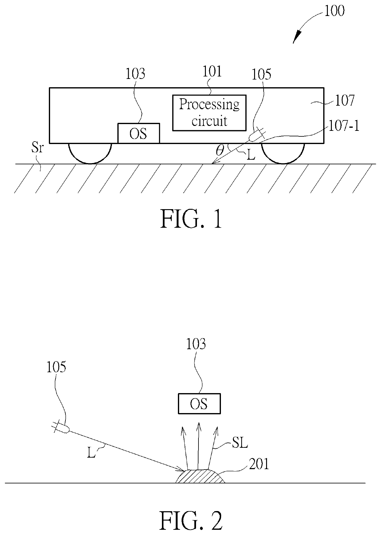
[0016]FIG. 1 is a block diagram illustrating an auto cleaner 100 according to one embodiment of the present invention. As illustrated in FIG. 1, the auto cleaner 100 comprises a processing circuit 101, an optical...


PUM


Abstract

An optical device, comprising: a processing circuit; a light source, configured to emit light to a surface; and an optical sensor, configured to sense optical data generated based on reflected light or scattering light of the light. The processing circuit computes a dirt level of the surface according to the optical data.

Description

CROSS REFERENCE TO RELATED APPLICATIONS[0001]This application is a continuation-in-part of U.S. application Ser. No. 17 / 393,424, filed on Aug. 4, 2021, which claims the benefit of U.S. Provisional Application No. 63 / 121,969, filed on Dec. 6, 2020. The contents of these applications are incorporated herein by reference.BACKGROUND OF THE INVENTION1. Field of the Invention[0002]The present invention relates to an optical device and a dirt level determining method, and particularly relates to an optical device and a dirt level determining method which can determine a dirt level according to optical data.2. Description of the Prior Art[0003]In recent years, an auto cleaner (or named as a sweeping robot, a robot cleaner) becomes more and more popular. However, the suction power of the auto cleaner needs to be manually adjusted, thus it is hard to select a suitable suction power. For example, if the suction power remains weak, the ground may not be clearly cleaned. On the opposite, if the ...

Claims


Application Information

Patent Timeline
IPC IPC(8): G06T7/00H04N5/225G05D1/02
CPCG06T7/0002G06T7/97H04N5/2256G05D1/0246G05D1/0219G05D2201/0215A47L2201/06A47L9/2805A47L9/2842A47L9/2894G06T7/0004H04N23/56
Inventor WANG, GUO-ZHENLAI, HUNG-CHING
Owner PIXART IMAGING INC
Why Eureka
Try Eureka