Imaging device and optical device

a technology of optical devices and optical devices, applied in the field of optical devices and imaging devices, can solve the problems of difficult effective removal of attached dust and the appearance of dust in taken images, and achieve the effect of removing attached dust on the whole region

Active Publication Date: 2009-06-18
NIKON CORP
View PDF5 Cites 21 Cited by
  • Summary
  • Abstract
  • Description
  • Claims
  • Application Information

AI Technical Summary

Benefits of technology

[0006]The present invention has been made due to considering these circumstances, and a purpose of the invention is to provide an imaging device and an optical device comprising the imaging device having an excellent dust removing capability.
[0015]According to the first aspect of the present invention and a manufacturing method thereof, it is available to remove the attached dust and the like on whole region of a surface of the light transmissive member effectively, by making available to bending vibration not only to the first direction, but also by making available to bending vibration to the second direction.
[0029]By the imaging device according to the second and the third aspects of the present invention, it is available to remove the attached dust on whole region of a surface of the light transmissive member effectively, by switching between the odd vibration mode and the even vibration mode.

Problems solved by technology

In recent years, in a lens interchangeable digital camera and the like, there are problems such that dust is shown in a taken image due to accretion of the dust on a surface of a filter of an image pick-up element.
However, according to conventional systems, since the anti-dust member is a circular shape, for covering the image pick-up element, an anti-dust member having large size is necessary which is contrary to a requirement for downsizing of the image pick-up device.
Also, in the conventional systems, because a vibration mode of the anti-dust member is not considered, it has been difficult effectively.

Method used


Image

  • Imaging device and optical device
  • Imaging device and optical device
  • Imaging device and optical device

Examples


first embodiment

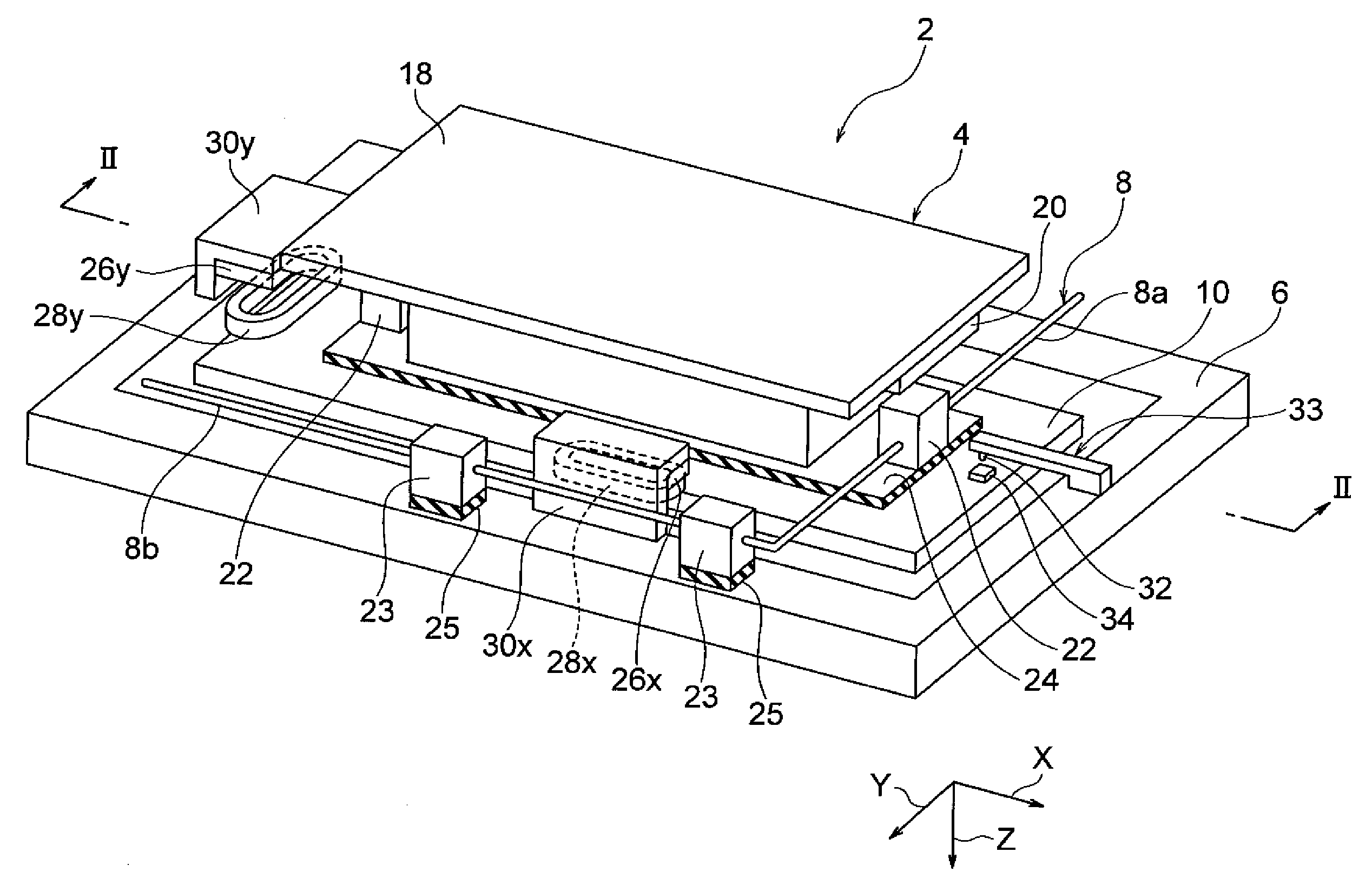
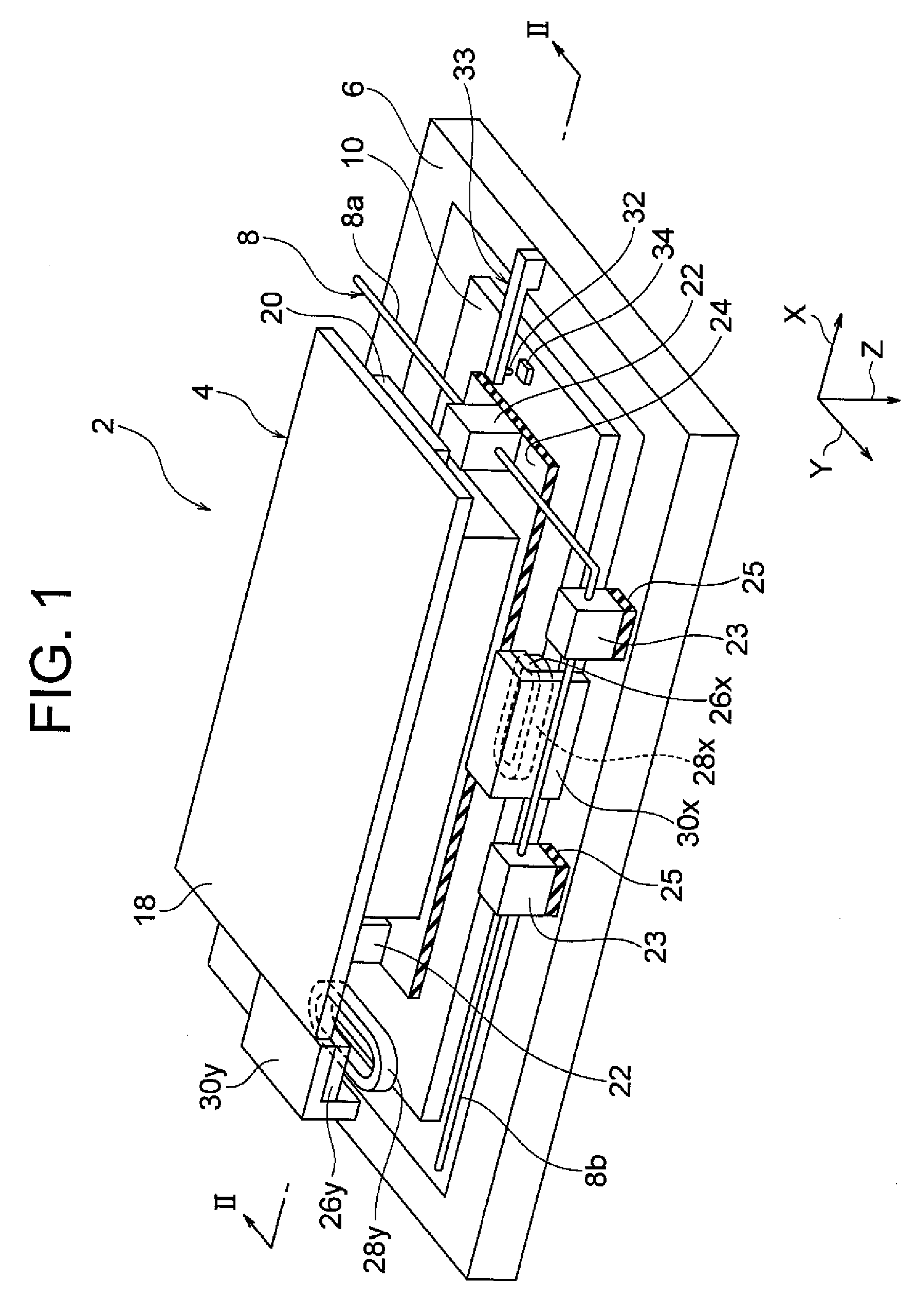
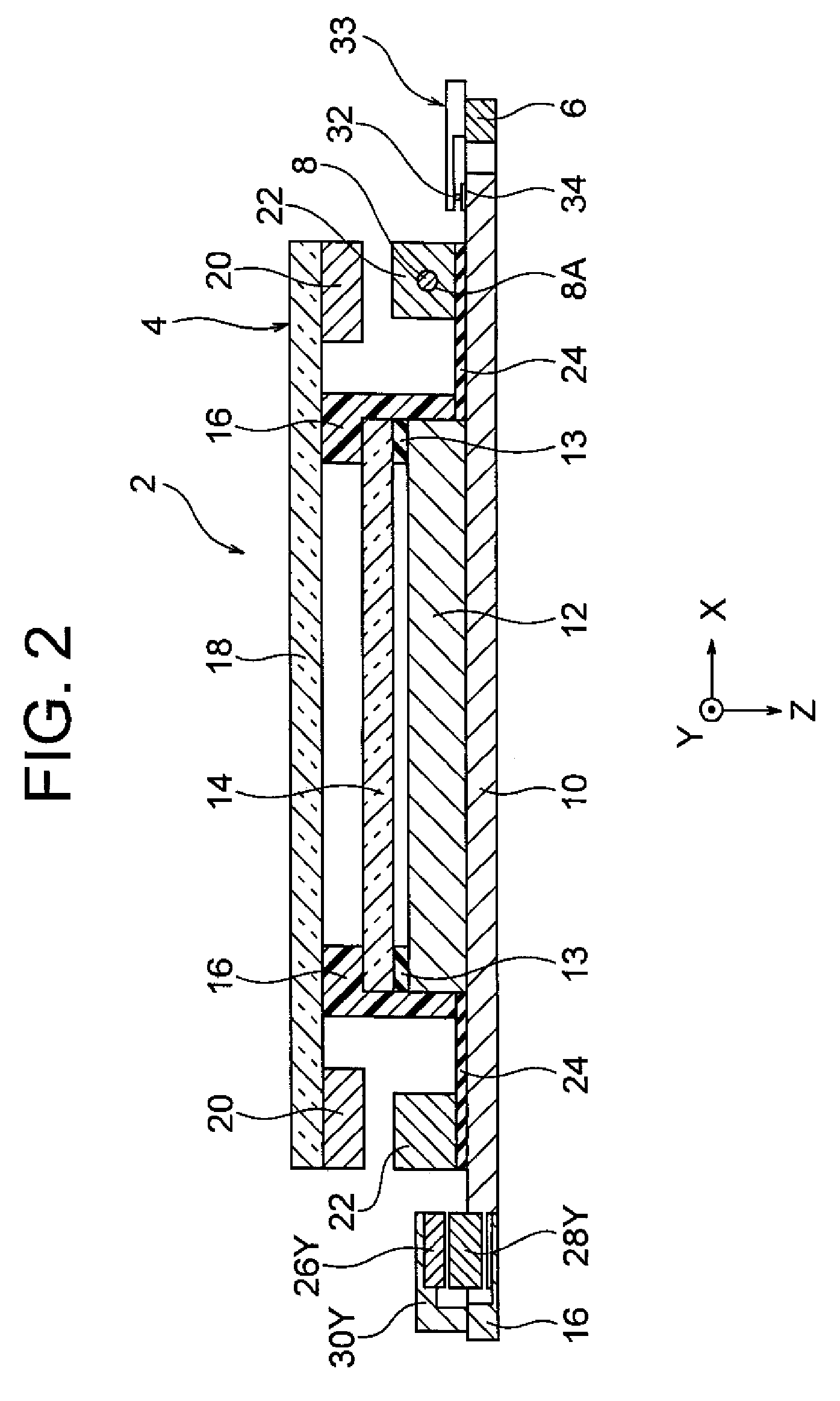
[0047]As shown in FIG. 1 and FIG. 2, a motion compensation device 2 according to one embodiment of the present invention, wherein an image pick-up element 12 is provided, comprises an image pick-up unit 4 being relatively movable toward X-axis and Y-axis directions with respect to a fixed portion 6. The fixed portion 6 is fixed to a body of camera 40 shown in FIG. 3. The image pick-up unit 4 is arranged movably along with X-axis and Y-axis directions vertical to an optical axis Z direction of optical lens group 48 contained in a lens barrel 42 which is detachably attached to the body of camera 40. Note that the X-axis and Y-axis are vertical.

[0048]As shown in FIG. 1 and FIG. 2, the image pick-up unit 4 comprises a movable plate 10 which is movable to the X-axis and the Y-axis directions with respect to the fixed portion 6. The image pick-up element 12 is fixed on a surface of center portion of the movable plate 10, and an optical low-pass filter (OLPE) 14 is provided thereon via a s...

second embodiment

[0092]Whole composition of the camera of the present embodiment is similar with the first embodiment shown in FIG. 3, therefore, overlapped explanation will be omitted.

[0093]As shown in FIG. 6 to FIG. 8, the image pickup element unit according to the present embodiment includes a substrate 10, and the image pickup element 12 is fixed on an upper face of center portion of the substrate 10. A case 17 is arranged at a circumference of the image pickup element 12, the case is detachably or not detachably fixed to a surface of the substrate 10.

[0094]The case 17 is composed of an insulating body, for example, such as synthetic resin or ceramic and the like, and an inner circumferential side attaching portion 17a and an outer circumferential side attaching portion 17b are formed at an upper face thereof in a step-like pattern. An outer circumference of optical member elements 30 having light transmissive property is attached to the inner circumferential side attaching portion 17a. As a res...

third embodiment

[0130]This third embodiment is similar with the second embodiment other than that, as shown in FIG. 11, a cross sectional constitution of an image taking element unit 4a differs a cross sectional constitution shown in FIG. 7. Therefore, specification of common portion therewith will be omitted and only difference points will be specified.

[0131]In the present embodiment, OPLF is composed by directly laminating a crystal plate 13, an infrared ray absorbing glass plate 14 and a crystal wavelength plate 15 and a crystal plate 18a. A width of the longitudinal direction L of the crystal plate 18a is enlarged with respect to a width of the other optical member elements 30. Then, the respective piezoelectric elements 20 are equipped on both side faces of the longitudinal direction L of the crystal plate 18a to which the optical member element 30 is not formed.

[0132]In the image pickup unit 4a according to the present embodiment, it is available to reduce whole size further, as compared from...


PUM


Abstract

An imaging device comprising a light transmissive member 18 having light transmissive character, a vibration member 20 causing bending vibration for the light transmissive member, a driving portion 56 for driving the vibration member 20, wherein the driving portion 56 causes bending vibration of the light transmissive member at a first frequency along with a first direction and causes bending vibration of the light transmissive member 18 at a second frequency along with a second direction which is different from said first frequency.

Description

BACKGROUND OF THE INVENTION[0001]1. Field of the Invention[0002]The present invention relates to an imaging device and an optical device.[0003]2. Description of the Related Art[0004]In recent years, in a lens interchangeable digital camera and the like, there are problems such that dust is shown in a taken image due to accretion of the dust on a surface of a filter of an image pick-up element. In order to solve such problems, a system has been developed wherein an anti-dust member is provided between an image pick-up element and an optical system to ensure dust-prevention for the image pick-up element and filters as well as removing the attached dust on the anti-dust member by vibration (refer to JP Patent Publication No. 2003-319222).[0005]However, according to conventional systems, since the anti-dust member is a circular shape, for covering the image pick-up element, an anti-dust member having large size is necessary which is contrary to a requirement for downsizing of the image ...

Claims


Application Information

Patent Timeline
Patent Type & Authority Applications(United States)
IPC IPC(8): G03B17/00
CPCG03B17/00G02B27/0006H04N5/2254H04N5/2171H04N23/811H04N23/52H04N23/55B08B7/02
Inventor MATSUMOTO, TSUYOSHI
Owner NIKON CORP
Why Eureka
Try Eureka