Filter for a hearing aid and a hearing aid

a filter and hearing aid technology, applied in the field of hearing aids, can solve the problems of clogging and baffled acoustic output, port clogging and baffle, and the risk of earwax or moisture entering the port, so as to eliminate the risk of the barrier element getting lost, prevent the passage of fluids, and facilitate the general user's use.

Active Publication Date: 2009-06-18
WIDEX AS
View PDF11 Cites 30 Cited by
  • Summary
  • Abstract
  • Description
  • Claims
  • Application Information

AI Technical Summary

Benefits of technology

[0020]This provides a hearing aid with a barrier element that combines superior barrier properties against the entry of earwax and moisture with superior acoustic properties. The barrier element may be integrated into the earwax guard or it can be arranged in series with the earwax guard to provide an extra line of defense.
[0024]The pores provide openings for conveying the sound. The small size of the pores prevents the passage of fluids.
[0025]According to an embodiment, the barrier element is fitted inside the earpiece so as to be inaccessible to the general user. This eliminates the risk of the barrier element getting lost, and thereby protects the more costly internal parts.

Problems solved by technology

With a hearing aid or an ear piece having an output port inserted into the ear canal of a user there is a risk of earwax or moisture entering the port.
The result is that the port clogs and baffles the acoustic output.
The earwax guard may not be effective to entirely prevent the entry of moisture.
As far as pertains the microphone port, there may also be a risk of entry of moisture and earwax, although there may be less exposure to earwax as the microphone port faces the surroundings rather than the ear canal.
A grid may be provided, although it may not be effective for protection against the entry of moisture.
With a hearing aid fitted with an earwax guard adapted for easy removal, there is the risk that the earwax guard accidentally is lost, or that the user removes it without inserting a new one, e.g. if he or she has no replacement available.
When using the hearing aid without the earwax guard there is a risk of earwax entering deeper into the hose and ultimately into the receiver, where it may clog the receiver membrane or it may accumulate on the integral acoustic filter, if present.
The same might happen if the earwax guard was not effective, i.e. if it was open for penetration of earwax.
In either case, the outcome is a costly service operation, involving disassembly or replacement of the receiver.
It is estimated that a major proportion of service issues with hearing aids is related to the entry of earwax or moisture into the output port.
Providing the receiver with an external acoustic filter complicates logistics.
However, a standard earwax guard necessarily must be acoustically transparent in order not to absorb energy and possibly distort the desired acoustic output in a non-controlled way.
Therefore general earwax guards may not be effective for preventing the entry of moisture.

Method used


Image

  • Filter for a hearing aid and a hearing aid
  • Filter for a hearing aid and a hearing aid
  • Filter for a hearing aid and a hearing aid

Examples


first embodiment

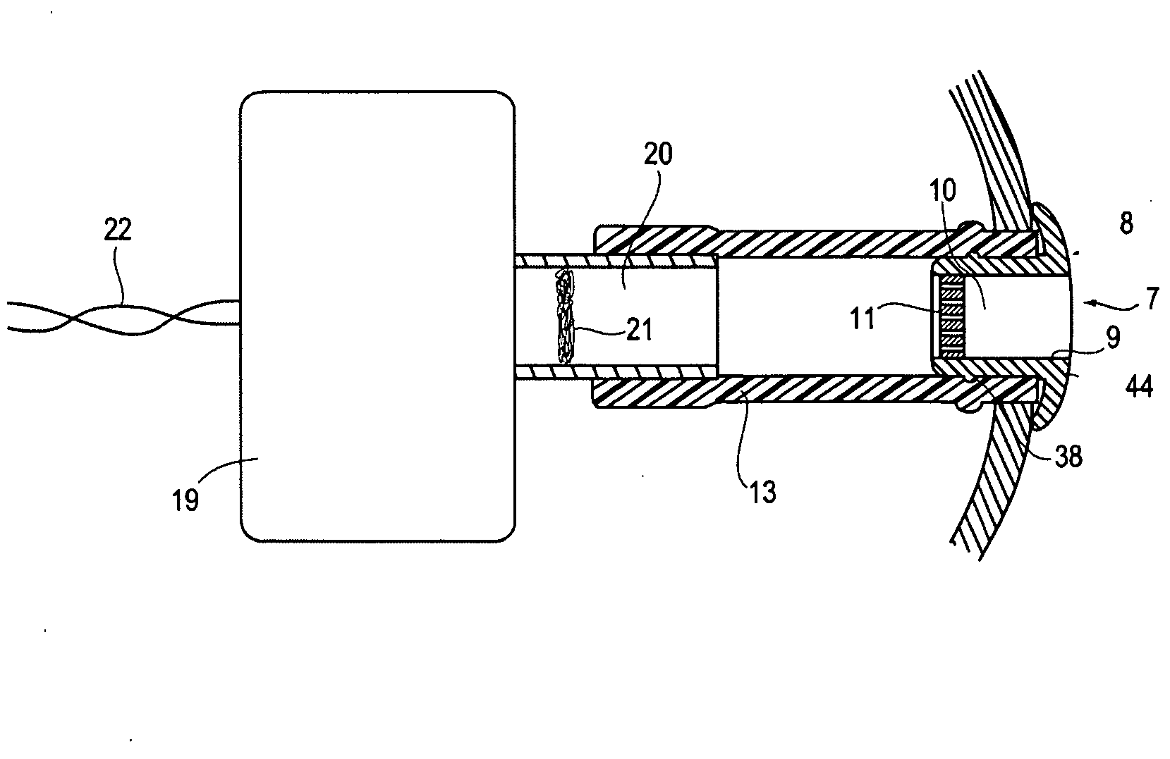
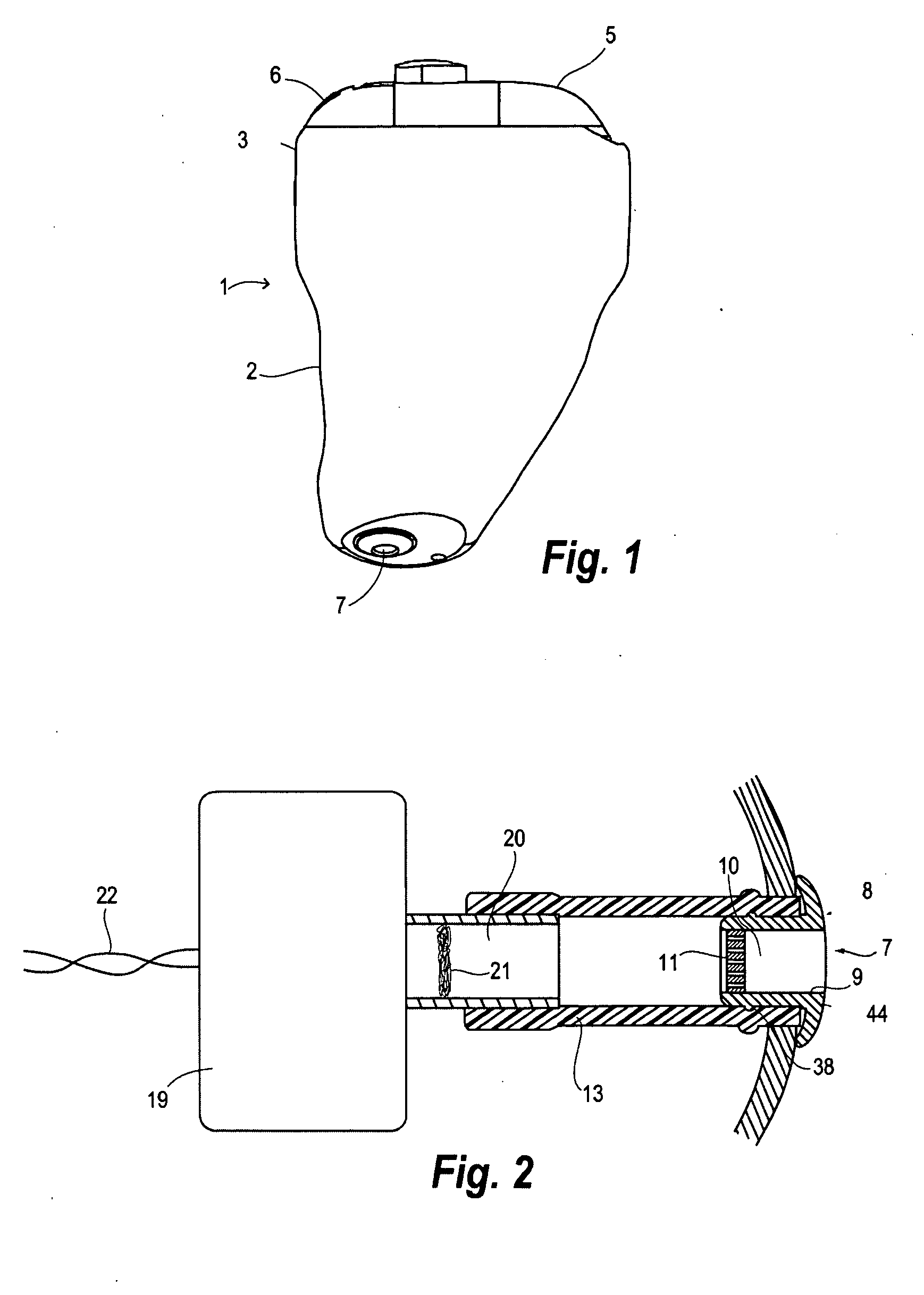
[0042]FIG. 2 illustrates the sound output segment of the hearing aid comprising a receiver body 19, leads 22 for electrical connection, a receiver stub 20, housing an acoustic filter 21, and a tube or hose 13, which connects the receiver stub 20 with an aperture in the shell 2, that defines the sound output port 7. Inserted in the hose 13 is a barrier element according to the invention, in the form of an earwax guard 8 which comprises a cylindrical body 9 having a through-going bore 10 which is partially closed at one end by an earwax retaining strainer 11. At the opposite end the cylindrical body 9 is provided with a round-going collar 44, which in the inserted position abuts against an end wall part of the shell 2. The earwax guard 8 is frictionally engaged with tube 13 by an annular bead 38 on the cylindrical body 9 and is thereby held in position during use of the hearing aid 1.

[0043]When a quantity of earwax has accumulated in the earwax guard 8 to significantly reduce the soun...

second embodiment

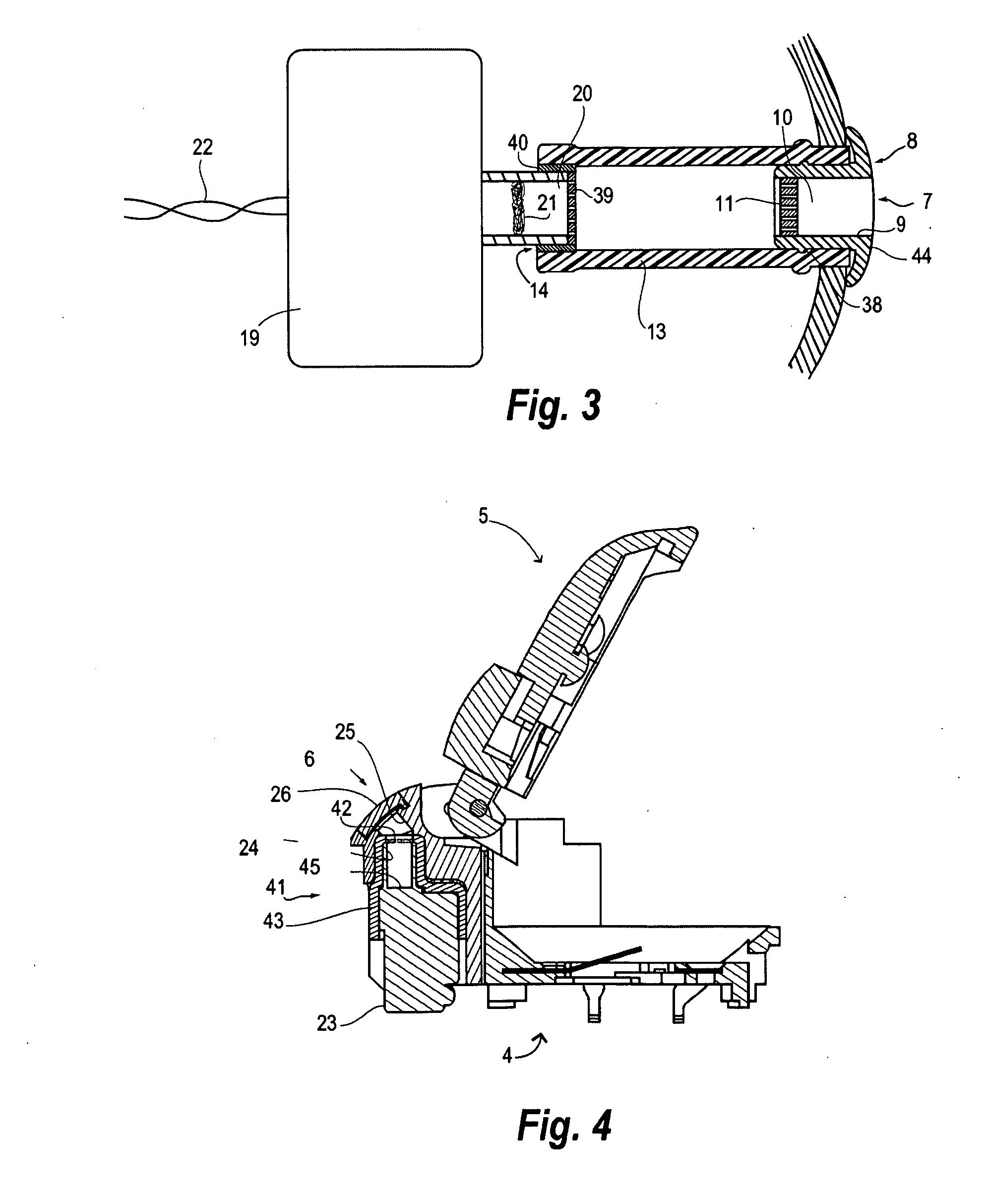
[0044]FIG. 3 illustrates the sound output segment of hearing aid 1 including a barrier element according to the invention in the form of a protection cap 14, which is mounted in the receiver stub 20 or in the hose 13. The protection cap 14 comprises a receiver protection strainer 39 in a supporting ring 40. The protection cap 14 serves as an additional barrier to protect the receiver from wax or sweat that for some reason enters the tube 13. This may for example happen if the earwax guard 8 falls out of the sound output port 7 during use of the hearing aid 1. Further, the presence of the protection cap 14 is advantageous in a situation where the user is out of earwax guards but still wants to use the hearing aid, or in case the user simply forgets to insert an earwax guard. The protection cap 14 will thus minimize the risk of receiver malfunction as a consequence of intruding earwax and sweat.

[0045]Contrary to the replaceable earwax guard 8, the protection cap 14 is an internal comp...

third embodiment

[0046]FIG. 4 shows a sub-assembly of hearing aid 1, mainly consisting of an electronics module 4, a microphone adaptor 41 and the lid 5. The microphone adaptor 41 comprises the sound inlet port 6, partially covered by a microphone grid 26, a sound inlet conduit 25, a microphone stub 24, a gasket 43, a microphone port 45, and a microphone 23. The microphone adaptor 41 further includes a barrier element according to the invention in the form of a microphone protection strainer 42, which is positioned in the vicinity of the microphone 23. In FIG. 4 the microphone protection strainer 42 is positioned just outside the microphone stub 24.

[0047]The strainer 11, the receiver protection strainer 39, and the microphone protection strainer 42 have surfaces which are modified to exhibit improved barrier properties towards aqueous and oily substances, as will be explained in greater detail below. The primary function of the barrier elements is to protect the receiver 19 and the microphone 23 fro...


PUM


Abstract

A hearing aid (1) comprises a receiver (19), an output port (6), a conduit (13) for conveying sound to the port and a barrier element (39) adapted for baffling entry of ear wax and moisture and for being acoustically transparent. The invention further provides a barrier element (39) for a hearing aid comprising a slab having an exterior surface and through openings for transverse transmission of sound, wherein the exterior surface is super-hydrophobic.

Description

RELATED APPLICATIONS[0001]The present application is a continuation-in-part of application no. PCT / DK2006 / 000470 filed on Aug. 31, 2006 and published as WO-A1-2008025355, the contents of which are incorporated herein by reference.BACKGROUND OF THE INVENTION[0002]1. Field of the Invention[0003]The present invention relates to hearing aids. The invention, more specifically, relates to a filter for a hearing aid.[0004]ITE hearings aids generally comprise a shell, which anatomically duplicates the relevant part of the user's ear canal. A receiver is placed in the shell in communication with an acoustic outlet port arranged at the proximal end, i.e. the end of the shell intended to be situated in the ear canal close to the tympanic membrane. The distal end of the shell, i.e. the opposite end, intended to be oriented towards the surroundings, is closed by a faceplate subassembly, connected to the receiver by leads. The faceplate subassembly incorporates a microphone, electronics, a batter...

Claims


Application Information

Patent Timeline
Patent Type & Authority Applications(United States)
IPC IPC(8): H04R25/00
CPCH04R25/654
Inventor VESTERGAARD, JORN EILEROLSEN, JORGEN MEJNERCHRISTENSEN, LEIF HOJSLETHAUGSHOJ, KENNETH B.
Owner WIDEX AS
Why Eureka
Try Eureka