Telescope for an imaging catheter

a technology for imaging catheters and telescopic devices, which is applied in the field of telescopic devices for imaging catheters, can solve the problems of difficult extension and retracting of telescopes, major deficiency of current designs, and inability to extend and retract existing telescope designs

Active Publication Date: 2009-06-18
ACIST MEDICAL SYST
View PDF6 Cites 100 Cited by
  • Summary
  • Abstract
  • Description
  • Claims
  • Application Information

AI Technical Summary

Problems solved by technology

This gap is a major deficiency of the current design.
Another short coming of existing telescope designs is that the telescope is not straight, which makes it difficult to extend and retract the telescope.
As a result, the existing telescope design is difficult to extend and retract.
This results in either a failed electrical connection or a mechanical defect in the drive cable which manifests itself in a non-uniformed rotation of the transducer and the associated image artifact.
Another short coming of exi...

Method used


Image

  • Telescope for an imaging catheter
  • Telescope for an imaging catheter
  • Telescope for an imaging catheter

Examples


Embodiment Construction

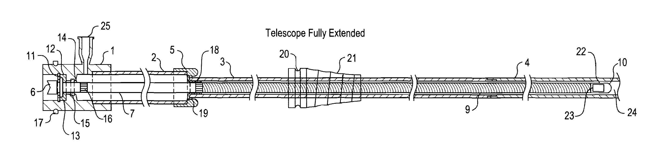
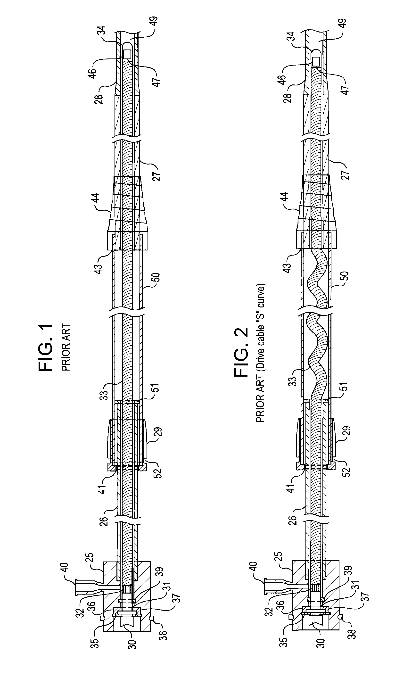
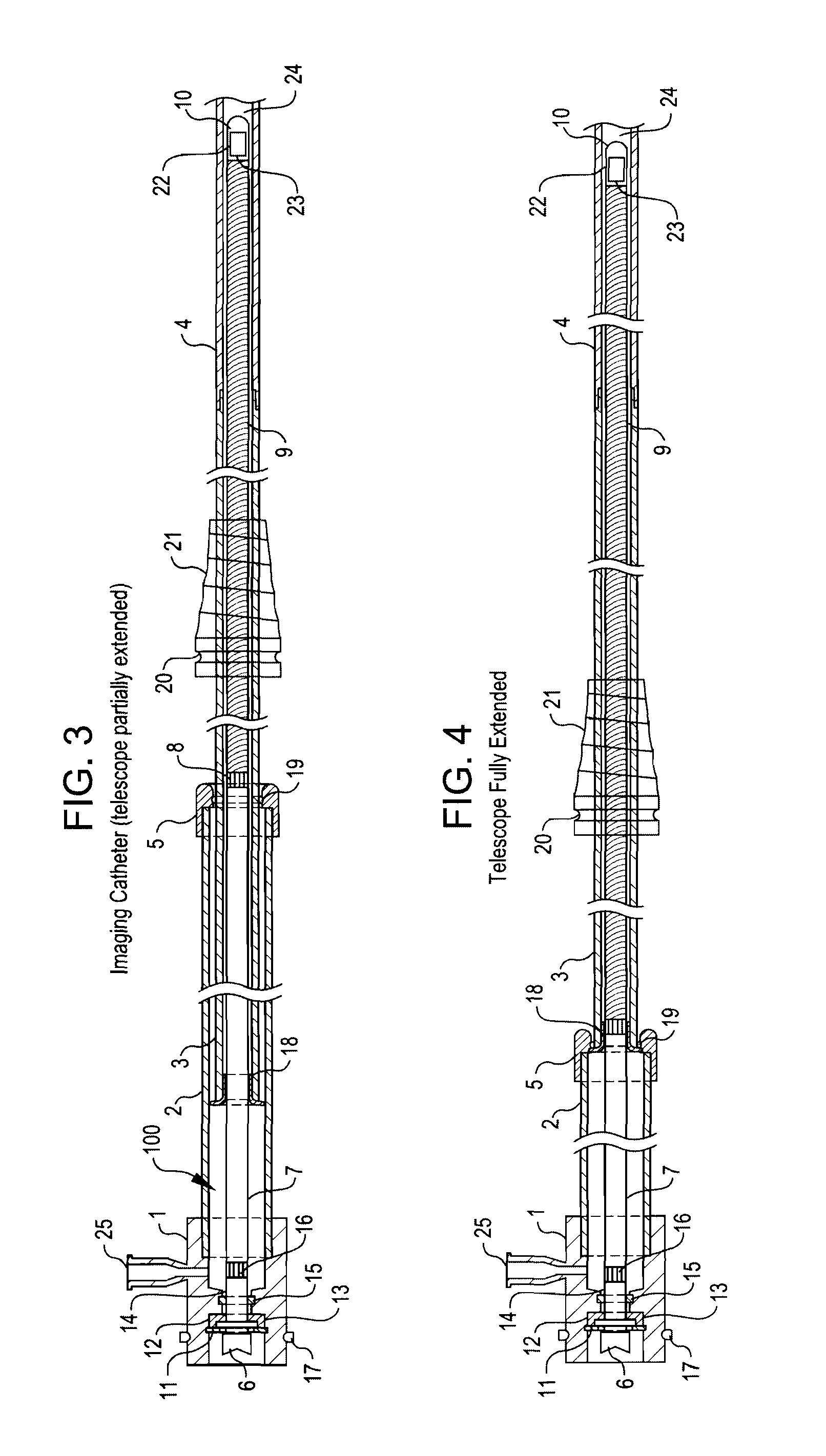
[0033]As will be seen from the foregoing, the embodiments of the present invention shown in FIGS. 3-6 include improvements to both the drive cable 7, 8 and 9 and the telescope. These improvements make it possible, without limitation, to eliminate failure mechanisms associated with collapsing of the telescope lumen onto the drive cable, to eliminate drive cable failures resulting from drive cable fold back in the telescoping section, to reduce friction within the telescope to improve its operation and to eliminate unnecessary components in the telescope section.

[0034]The drive cable 100, according to these embodiments of the present invention, contains both a proximal rigid section 7 and a distal flexible section 9. The rigid section is constructed of a stainless steel or other suitable material hypo tube that is welded or in some other way bonded to the flexible drive cable 9 that is similar to those used in current mechanically scanning imaging catheter designs. The rigid section 7...


PUM


Abstract

A catheter has a proximal end and a distal end and comprises an outer tube having a proximal end, an inner sheath slidingly received within the outer tube and extending distally from the outer tube, and a rotatable shaft extending from the proximal end of the outer tube to within the inner sheath. The rotatable shaft is axially fixed with respect to the outer tube and axially moveable within and with respect to the inner sheath. The rotatable shaft includes a proximal substantially rigid section and a distal flexible section. The catheter further includes a working element carried on the distal flexible section of the rotatable shaft.

Description

PRIORITY CLAIM[0001]The present application claims the benefit of copending U.S. Provisional Patent Application Ser. No. 61 / 008,120, filed Dec. 17, 2007, which application is incorporated herein by reference in its entirety.BACKGROUND OF THE INVENTION[0002]Intravascular ultrasound (IVUS) catheters provide a means of imaging internal structures in the body. Coronary IVUS catheters are used in the small coronary arteries of the heart to visualize coronary artery disease (CAD). There are other non-IVUS invasive imaging systems and catheters, such as optical coherence tomography OCT and Optical Frequency Domain Imaging (OFDI), that also provide a means of imaging internal structures within the human body. IVUS catheters (see FIG. 1) use transducers 46 to create pressure waves, other imaging systems use different imaging energy sources. Both OCT and OFDI use laser light as the imaging source.[0003]There are two type of coronary IVUS catheters: mechanically scanned and electronically scan...

Claims


Application Information

Patent Timeline
IPC IPC(8): A61B8/14
CPCA61B5/0062A61B5/0084A61B8/4461A61B8/12A61B8/445A61B5/02007
Inventor MOORE, THOMAS C.
Owner ACIST MEDICAL SYST
Why Eureka
Try Eureka