
Network redundancy check application program management method

Inactive Publication Date: 2009-06-18
MOXA INC
View PDF3 Cites 4 Cited by
  • Summary
  • Abstract
  • Description
  • Claims
  • Application Information

AI Technical Summary

Benefits of technology

[0015]According to another aspect of the present invention, the invention uses the driver to virtualize two IP addresses for the main transmission path and the sub-transmission path into one single COM port. Thus, the application program of the master end needs only to access data through the virtual COM port. When upgrading an Ethernet having only one IP address to two IP addresses, it is not necessary to create a new application program to match the two IP addresses, thereby saving much application program developing time and labor.

Problems solved by technology

Because commercial Ethernet systems cannot fit the requirement of industrialization for high reliability, they are not practical for use in a hard and unexpected industrial environment.
1. Because the dual-path redundancy check system type Ethernet system has two transmission paths (the main transmission path B and the sub-transmission path C), the user of the master end A needs to manage and control the two transmission paths. Further, when the master end A needs to open different COM ports subject to different transmission conditions, the manager needs to manage or monitor twice the amount of COM ports. Therefore, the manager of the dual-path redundancy check system type Ethernet system spends a doubled amount of time to control the transmission paths.
2. Similarly, when the supplier of the master end A or slave end E is going to create a related application program, the supplier must design the path judging algorithm subject to the COM ports under the dual-path architecture. The supplier needs to spend much time to create new management program for judging switching among COM ports under this dual-path architecture.

Method used


Image

  • Network redundancy check application program management method
  • Network redundancy check application program management method
  • Network redundancy check application program management method

Examples


Embodiment Construction

[0032]Reference will now be made in detail to preferred embodiments of the invention, exemplars of which are illustrated in the accompanying drawings.

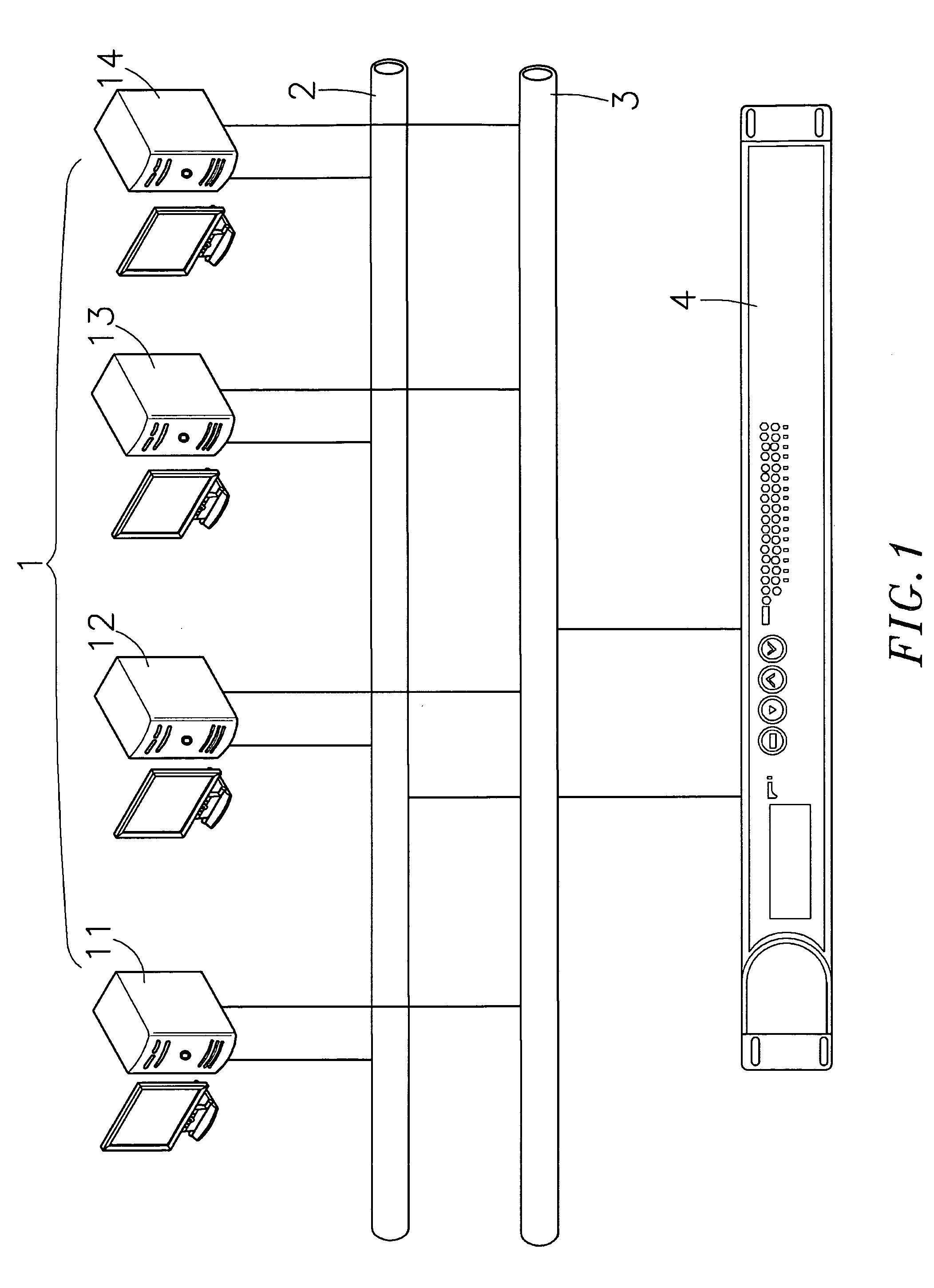
[0033]Referring to FIG. 1, a dual-path, redundancy type Ethernet system in accordance with the present invention is shown comprised of a master-end 1, a main transmission path 2, a sub-transmission path 3, and an intermediary device 4. The master-end 1 comprises a plurality of workstations 11˜14. The main transmission path 2 and the sub-transmission path 3 are designed subject to redundancy check required for industrial Ethernet application.

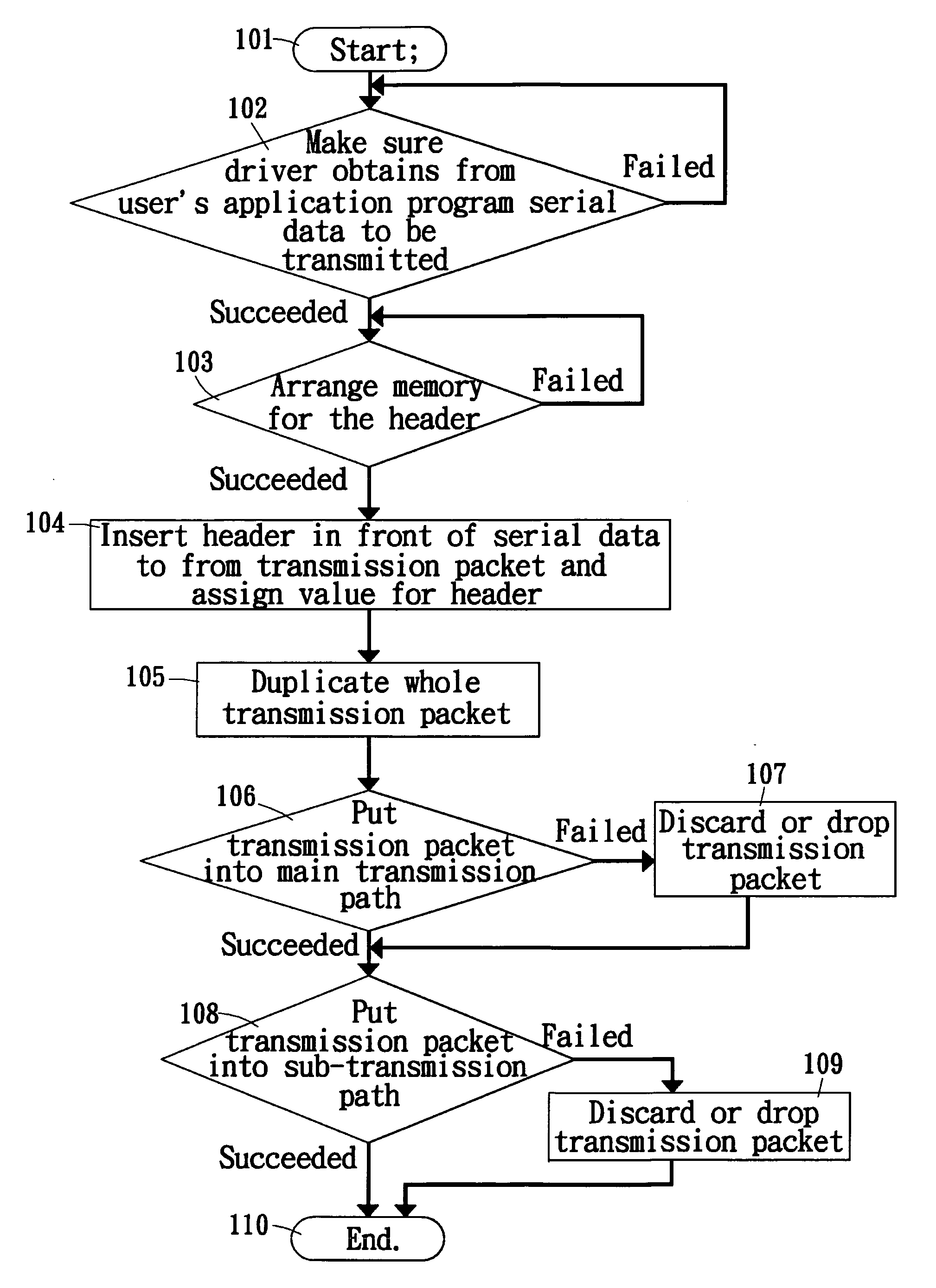
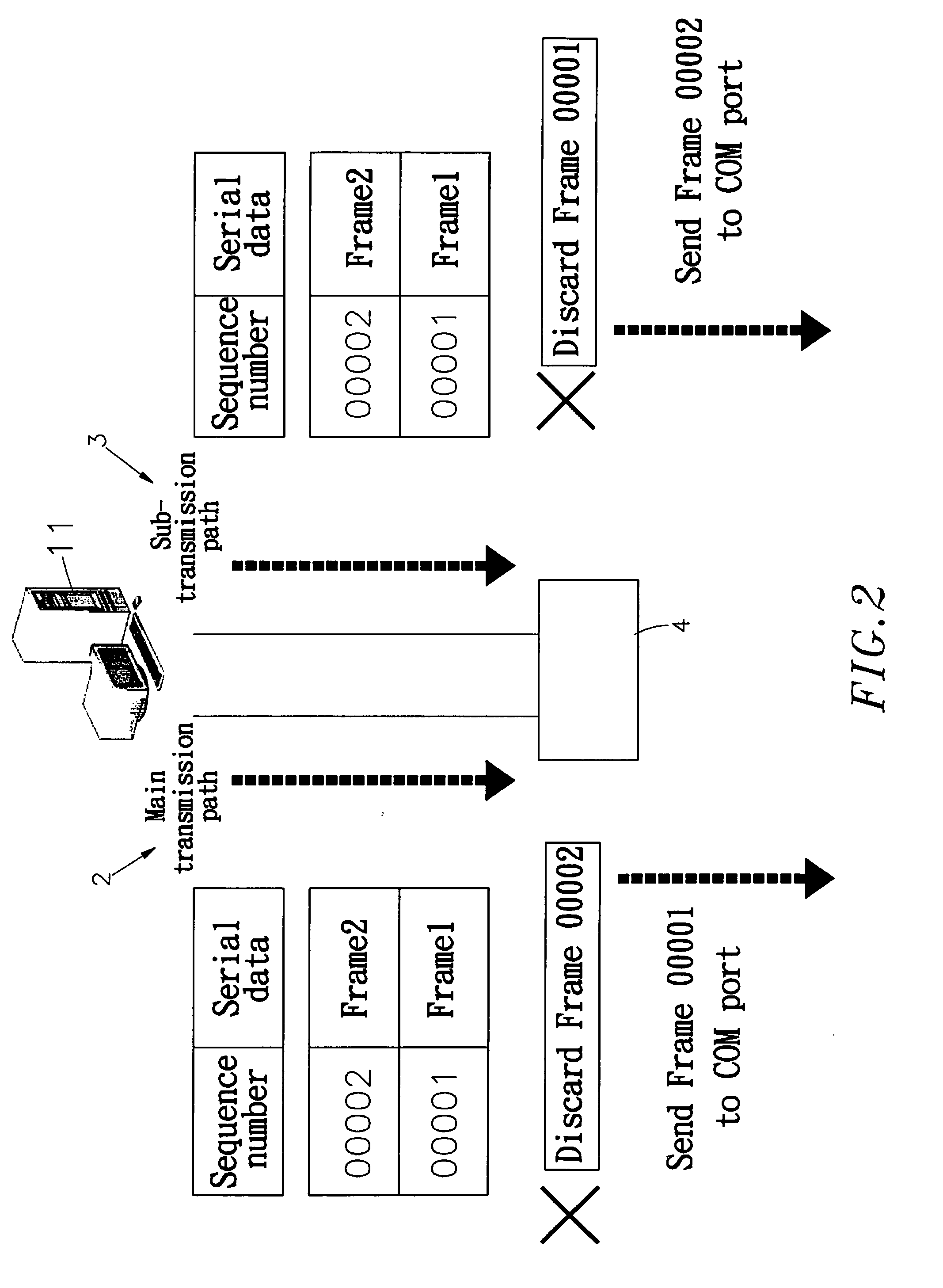
[0034]FIG. 2 is a schematic drawing of the present invention, showing data transmission from the master-end to the intermediary device. FIG. 3 is a schematic drawing of the present invention, showing a packet data transmitted between the master-end and the intermediary device. FIG. 4 is a schematic drawing of the present invention, showing data transmitted from the master-end and processed into a da...


PUM


Abstract

For use in a dual-path network system comprising a master end, a main transmission path, a sub-transmission path, an intermediary device, and a slave end, a network redundancy check application program management method is disclosed to virtualize COM ports of multiple IP addresses in the master end into one single virtualized COM port by means of a driver in the master end so that the user / user's application program needs only to manage / monitor the virtualized COM port. Through the driver and the firmware formed in the intermediary device, the invention covers all operation modes, and the user / user's application program needs not to worry about system complication resulted from the redundancy check system. Under the network architecture of the present invention, the master end enjoys the high stability of dual-path, and the manager needs not to manage a big number of COM ports.

Description

BACKGROUND OF THE INVENTION[0001]1. Field of the Invention[0002]The present invention relates to management of network redundancy check application program and more particularly, to a network redundancy check application program management method which virtualizes COM ports of multiple IP addresses in the master end into one single virtualized COM port by means of a driver in the master end, and enables the redundancy check system to check whether the serial data to be transmitted through the virtualized COM port is effective or duplicated, thus obtaining the benefits of having a redundancy check system and managing one single COM Port.[0003]2. Description of the Related Art[0004]Following progress of communication technology, communication networks are well developed. LAN (Local Area Network) and WAN (Wide Area Network) are the original categories of networks categorized subject to their scope and scale. A LAN connects network devices over a relatively short distance. A WAN is a ge...

Claims


Application Information

Patent Timeline
IPC IPC(8): G06F13/00
CPCH04L12/40182H04L69/161H04L69/16H04L2012/4026
Inventor SHIH, PI-YUANSUEN, JER-HONGSHAO, SHIH-HUI
Owner MOXA INC
Learn More