Exhaust purification apparatus for engine

a technology for purifying apparatus and exhaust, which is applied in the direction of machine/engine, electrical control, exhaust treatment, etc., can solve the problems of nox catalyst temperature falling below the activation temperature, nox catalyst exhaust purification efficiency drastically decreasing, and nox emission amount increasing

Inactive Publication Date: 2009-06-25
MITSUBISHI FUSO TRUCK AND BUS CORPORATION
View PDF10 Cites 41 Cited by
  • Summary
  • Abstract
  • Description
  • Claims
  • Application Information

AI Technical Summary

Benefits of technology

[0010]An aspect of the present invention is directed to an exhaust purification apparatus for an engine, comprising: a selective reduction-type NOx catalyst that is interposed in an exhaust passage of an engine and selectively reduces NOx contained in exhaust gas of the engine by using ammonia as a reducing agent; EGR means for recirculating exhaust gas of the engine to an intake side of the engine; exhaust-purification-efficiency estimation means for estimating exhaust purification efficiency of the NOx catalyst with respect to NOx; target-exhaust-purification-efficiency calculation means for calculating target exhaust purification efficiency with respect to NOx on the basis of an operational state of the engine; and control means for controlling the EGR means to compensate a decrease amount of the estimated exhaust purification efficiency to the target exhaust purification efficiency.

Problems solved by technology

However, depending upon vehicle running conditions such as traffic jams in urban districts or environmental conditions such as cold regions in which outdoor air temperature is low, the temperature of the NOx catalyst may fall below the activation temperature.
There has been the problem that, in such a low temperature range, the exhaust purification efficiency of the NOx catalyst with respect to NOx drastically decreases, and that a NOx emission amount into the atmosphere is increased.
As Document 1 says, the technology described is only capable of lowering the lower limit of a temperature rage, in which the exhaust purifying operation that selectively reduces NOx can be achieved, to around 180 degrees centigrade, and is not capable of dramatically improving such exhaust purification performance in the low temperature range.
For this reason, the technology described in Document 1 has the problem that the exhaust purification apparatus becomes greatly complicated in configuration and then that the production cost is inevitably increased.

Method used


Image

  • Exhaust purification apparatus for engine
  • Exhaust purification apparatus for engine
  • Exhaust purification apparatus for engine

Examples


Embodiment Construction

[0015]An exhaust purification apparatus for an engine according to one embodiment of the present invention will be described below in details with reference to the attached drawings.

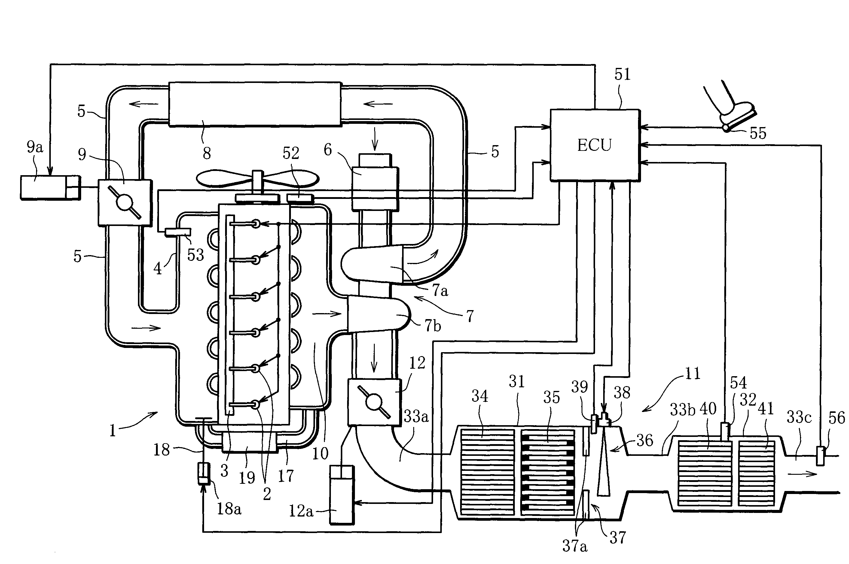
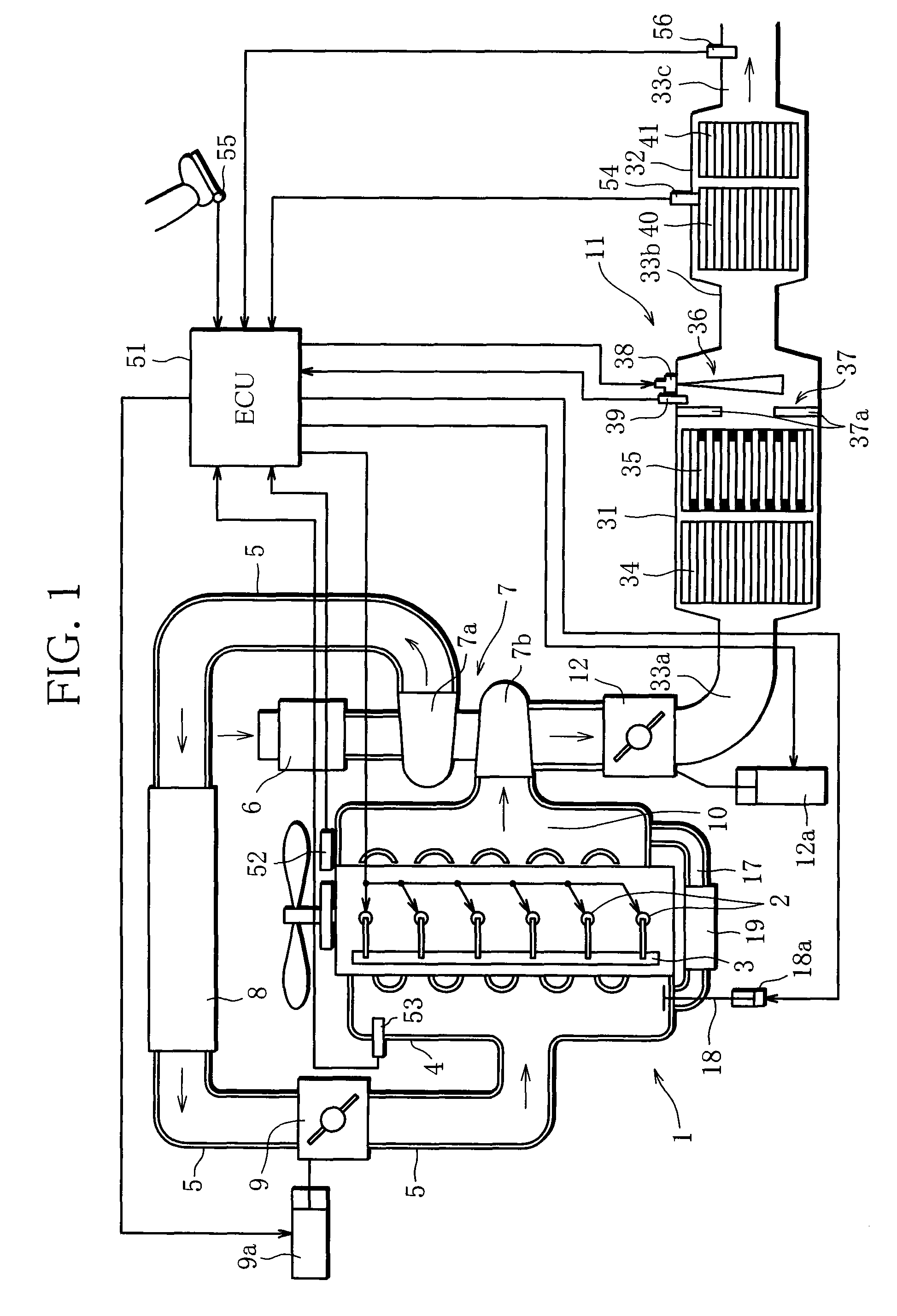
[0016]FIG. 1 is a view showing the entire configuration of the exhaust purification apparatus for an engine according to the present embodiment. An engine 1 is constructed as an in-line six-cylinder diesel engine that is installed in a vehicle. A fuel injection valve 2 is provided to each cylinder of the engine 1. The fuel injection valves 2 are supplied with pressure fuel from a common rail 3 and open with timing appropriate to an operational state of the engine 1 to inject the fuel into the cylinders.

[0017]An intake manifold 4 is mounted on an intake side of the engine 1. In an intake passage 5 connected to the intake manifold 4, there are interposed an air cleaner 6, a compressor 7a of a turbocharger 7, an intercooler 8, and an intake throttle valve 9 that is driven to open and close by an actuator 9a...


PUM


Abstract

An exhaust purification apparatus for an engine comprises a selective reduction-type NOx catalyst that is interposed in an exhaust passage of the engine and selectively reduces NOx contained in exhaust gas of the engine, an EGR device that recirculates exhaust gas of the engine to an intake side of the engine, an exhaust-purification-efficiency estimation unit that estimates exhaust purification efficiency of the NOx catalyst with respect to NOx, a target-exhaust-purification-efficiency calculation unit that calculates target exhaust purification efficiency with respect to NOx on the basis of an operational state of the engine, and a control unit that controls the EGR device to compensate a decrease amount of the estimated exhaust purification efficiency to the target exhaust purification efficiency.

Description

BACKGROUND OF THE INVENTION[0001]1. Field of the Invention[0002]The present invention relates to an exhaust purification apparatus for an engine, and more specifically, to an exhaust purification apparatus in which a selective reduction-type NOx catalyst that selectively reduces NOx contained in exhaust gas by using ammonia as a reducing agent is interposed in an exhaust passage of an engine.[0003]2. Description of the Related Art[0004]A NOx catalyst that is interposed in the exhaust passage of an engine and selectively reduces NOx contained in exhaust gas has been known as a device for purifying engine exhaust. When this kind of a selective reduction-type NOx catalyst is utilized, urea-water is injected from an injection nozzle that is set upstream of the NOx catalyst in the exhaust passage. The injected urea-water is hydrolyzed by exhaust gas heat and the water vapor contained in exhaust gas, and ammonia (NH3) is produced. By using the ammonia (NH3) thus produced as a reducing age...

Claims


Application Information

Patent Timeline
Patent Type & Authority Applications(United States)
IPC IPC(8): F01N9/00
CPCF01N3/035F02D41/1462F01N3/2066F01N11/00F01N2550/02F01N2610/02F01N2900/1621F02B29/04F02B37/00F02D41/0047F02D41/0072F02D41/0235F02D41/1463F02D41/1465F02D2250/36F02M25/0718Y02T10/47Y02T10/24F01N13/0097F01N13/009F01N3/106F02M26/15Y02T10/12Y02T10/40
Inventor SUZUKI, AKIRA
Owner MITSUBISHI FUSO TRUCK AND BUS CORPORATION
Why Eureka
Try Eureka