Hydraulic system

a technology of hydraulic system and valve body, applied in the direction of fluid couplings, positive displacement liquid engines, couplings, etc., can solve the problems of unnecessary efficiency losses for the vehicle, variable displacement pumps generally have only a limited suction capacity, and efficiency losses generally follow, so as to achieve the advantage of cost and development complexity, and the vehicle is considered to be saved. , the effect of reducing the number of valves

Active Publication Date: 2009-06-25
DEERE & CO
View PDF4 Cites 29 Cited by
  • Summary
  • Abstract
  • Description
  • Claims
  • Application Information

AI Technical Summary

Benefits of technology

[0017]A hydraulic system according to the invention has the advantage that, through the combination of various necessary low-pressure hydraulic circuites, considerable line savings for the vehicle can sometimes be obtained, since the supply of the different hydraulic components or consuming units can be realized in a relatively speed-independent and demand-driven manner by a main hydraulic circuit and

Problems solved by technology

However, such a fixed displacement pump must be designed to provide sufficient volumetric flow rate at idle and, as the engine speed increases, increasingly deliver excess unused hydraulic fluid into the tank.
This produces unnecessary efficiency losses for the vehicle.
However, these variable displacement pumps generally have only a limited suction capacity, on account of which charge pumps are used, which supply or charge these variable displacement pumps with low-pressure

Method used


Image

  • Hydraulic system
  • Hydraulic system
  • Hydraulic system

Examples


Embodiment Construction

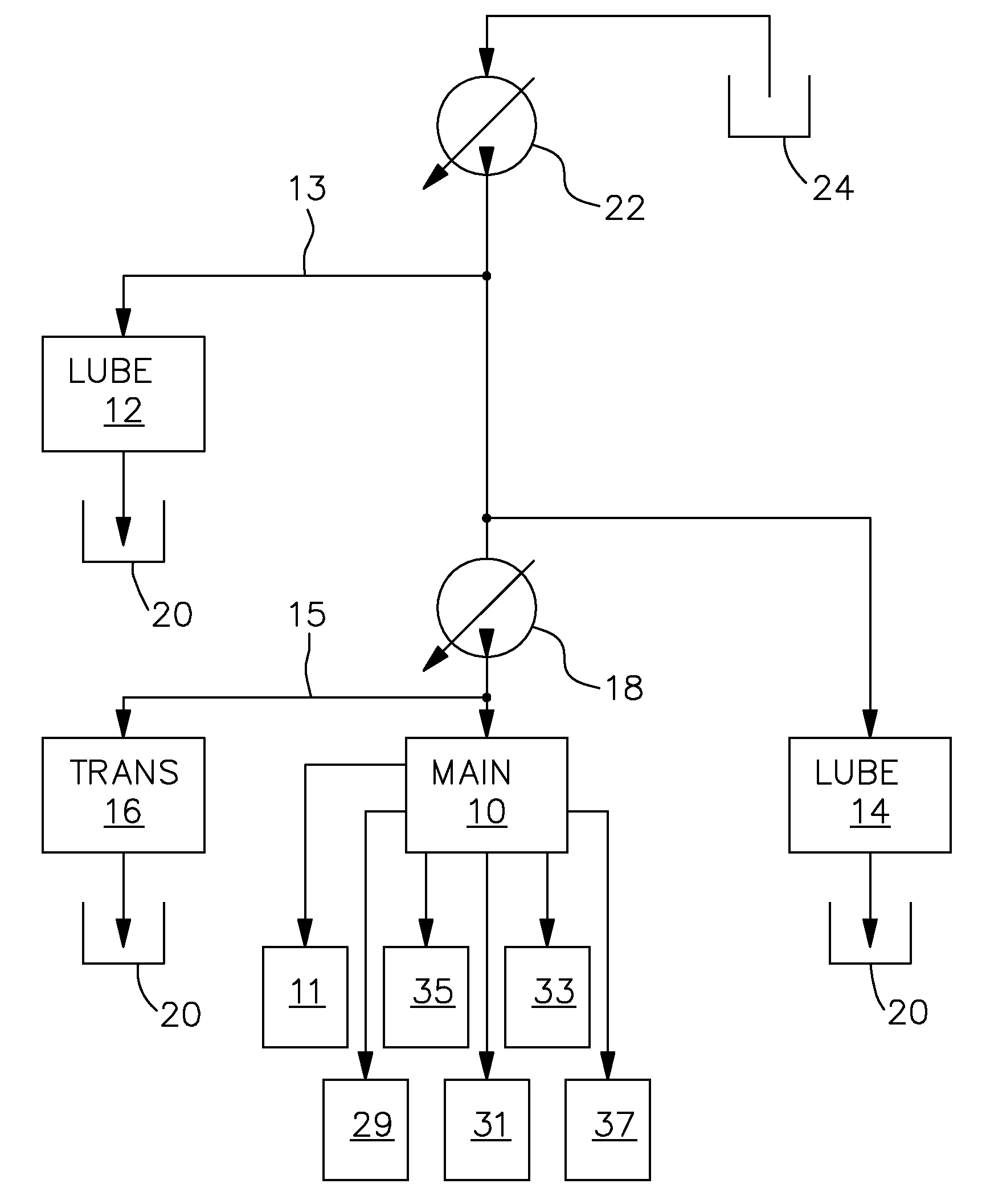
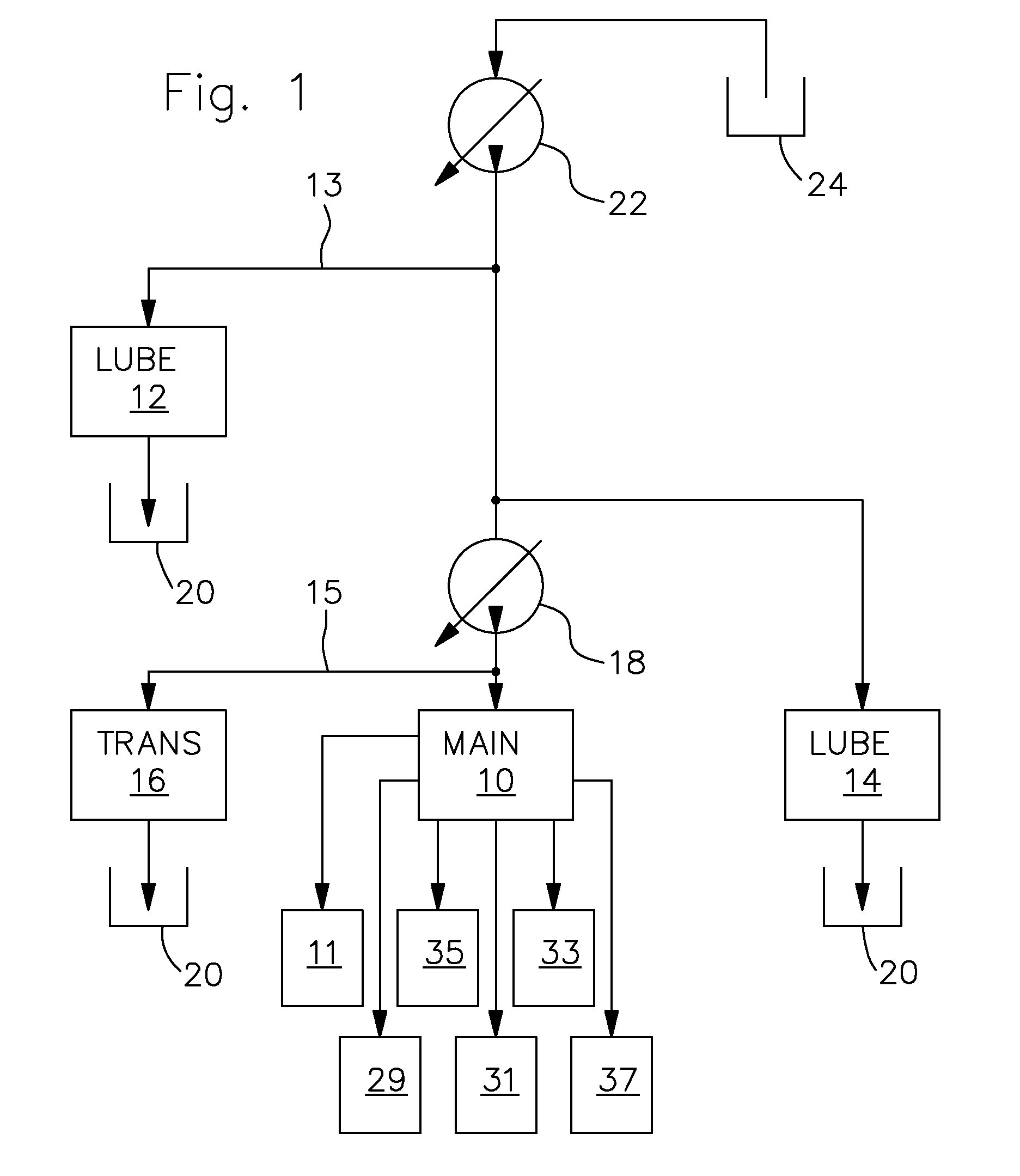
[0021]Referring to FIG. 1, the hydraulic system includes a main hydraulic circuit 10, a lubricating hydraulic circuit 12, 14, and a transmission shift control circuit 16. An variable displacement main hydraulic pump 18, for instance an adjustable or variable axial piston pump supplies the main hydraulic circuit 10. The individual hydraulic circuits 10, 12, 14, 16 are connected to corresponding return-flow reservoirs or hydraulic tanks 20, into which excess hydraulic fluid can be returned or drained. A branch line 15 communicates a portion of the hydraulic fluid delivered by the main hydraulic pump 18 to the transmission shift control circuit 16. The transmission shift control circuit controls the shifting of a transmission (not shown). A variable displacement charge pump 22 is connected to a hydraulic tank 24 and provides charge pressure to the main pump 18, and to the lubricating hydraulic circuit 12 via branch line 13. This hydraulic system is preferably used on agricultural machi...


PUM


Abstract

A hydraulic system for an agricultural vehicle is proposed. The hydraulic system comprises a main hydraulic circuit, which is fed with hydraulic fluid by a main hydraulic pump, a variable displacement charge pump which supplies charge pressure to the main hydraulic pump, and a lubricating hydraulic circuits. In order to keep efficiency losses on the vehicle to a minimum, particularly at high engine speeds, part of the hydraulic fluid delivered by the charge pump can be diverted to the lubricating hydraulic circuit.

Description

FIELD OF THE INVENTION[0001]The invention relates to a hydraulic system for an agricultural vehicle.BACKGROUND OF THE INVENTION[0002]In mobile work machines or agricultural vehicles, it is customary for the hydraulic components to be supplied by separate hydraulic circuits, such as a main hydraulic circuit or a transmission hydraulic circuit. Depending on the design type, the main hydraulic circuit is divided into different circuits or branches in order to supply steering, brake and other hydraulic components with hydraulic fluid.[0003]A transmission hydraulic circuit normally includes both a transmission shift control circuit and a lubricating hydraulic circuit, so that both the transmission shifting and the lubrication and cooling of the bearings and other moving transmission parts are ensured.[0004]Transmission hydraulic circuits are normally supplied by a cheap and simple fixed displacement pumps. However, such a fixed displacement pump must be designed to provide sufficient vol...

Claims


Application Information

Patent Timeline
IPC IPC(8): F04B49/00F04B41/06
CPCF04B23/10F04B23/04F16H61/0021F16H2061/0037
Inventor BITTER, MARCUSNORDHOFF, HANDRIKOBERST, KARSTEN
Owner DEERE & CO
Why Eureka
Try Eureka