System and method for manufacturing optical display

a technology of optical display and manufacturing method, which is applied in the field of systems and methods for manufacturing optical displays, can solve problems such as quality degradation, and achieve the effects of reducing the number of working processes, simplifying the packing operation, and reducing the work load

Inactive Publication Date: 2009-06-25
NITTO DENKO CORP
View PDF5 Cites 86 Cited by
  • Summary
  • Abstract
  • Description
  • Claims
  • Application Information

AI Technical Summary

Benefits of technology

[0012]The effects of the invention are described below. The optical display includes at least the optical film and the optical display unit. The belt and sheet-shaped product includes at least an optical film layer and optionally, for example, a protective film layer. The belt and sheet-shaped product is long and provided in the form of a roll. The belt and sheet-shaped product is fed from the roll, when whether or not defects such as stains, scratches and cracks are present is detected by the detection means.
[0013]According to the result of the detection, the belt and sheet-shaped product is cut into specific size pieces. The “specific size” depends on the size of the optical display product. When a certain defect is found as a result of the detection, for example, the cutting means is controlled such that the defect can be removed while specific size cut pieces can be produced. The sheet-shaped product obtained by cutting is then transferred to a sticking process. The transferred sheet-shaped product is stuck to the optical display unit by the sticking means. All of these means are placed on a continuous manufacturing line.
[0014]In the above manufacturing system, desired size pieces can be directly obtained by cutting from the belt and sheet-shaped product having the optical film and each stuck to the optical display unit. Therefore, a roll of the belt and sheet-shaped product can be directly packed and delivered to panel makers in contrast to the conventional technique where the belt and sheet-shaped product is subjected to punching, and punched sheet-shaped products are carefully packed and supplied to panel makers. Packing the roll allows easy selection of the packing material, allows simple packing operation with no need of a conventional packing tool or instrument for piling and packing sheet-shaped cut products and allows a reduction in the work load. There is also no need to perform the conventional end face working, which is also significantly advantageous for optical film component makers because of a reduction in the number of working processes.
[0015]Panel makers to which the products are supplied can easily perform the unpacking so that the work load can be reduced. Transferring the roll can also reduce the occurrence of scratches, cracks and so on and can prevent quality degradation.
[0016]In addition, the packing material can be simple, and the packing material cost and the occurrence of scratches, cracks and so on during the transportation can be reduced, so that the cost performance of the whole of the product can be significantly increased. It is also unnecessary for optical film component makers to cut sheet-shaped products depending on the type and size of the final optical display product or to stock and manage individual sheet-shaped products. The belt and sheet-shaped product itself (in the form of a raw roll) can be stored and managed so that inventory control can be simplified and that control management can be significantly improved. This is also advantageous for panel makers, because it is possible to stock and manage only a single type or few types of row rolls of the belt and sheet-shaped product and to cut a necessary portion (size) in a necessary form for use in manufacture so that expensive optical film stocks can be significantly reduced. According to the invention, therefore, both makers can significantly increase the productivity.
[0017]In a preferred embodiment of the invention, the belt and sheet-shaped product has a pressure-sensitive adhesive for sticking to the optical display unit and a release film for protecting the pressure-sensitive adhesive, and the system further includes separating means that separates the release film from the belt and sheet-shaped product before the detection of a defect by the detection means and cleaning means that cleans the belt and sheet-shaped product from which the release film has been separated, before the detection of a defect by the detection means.

Problems solved by technology

When a pile of several pieces is packed, the squeezing out of the pressure-sensitive adhesive layer (pressure-sensitive adhesive) can cause sticking of the layered sheet-shaped products and can further cause scratches or stains on the surface of the sheet-shaped products to degrade the quality.

Method used


Image

  • System and method for manufacturing optical display
  • System and method for manufacturing optical display
  • System and method for manufacturing optical display

Examples


Embodiment Construction

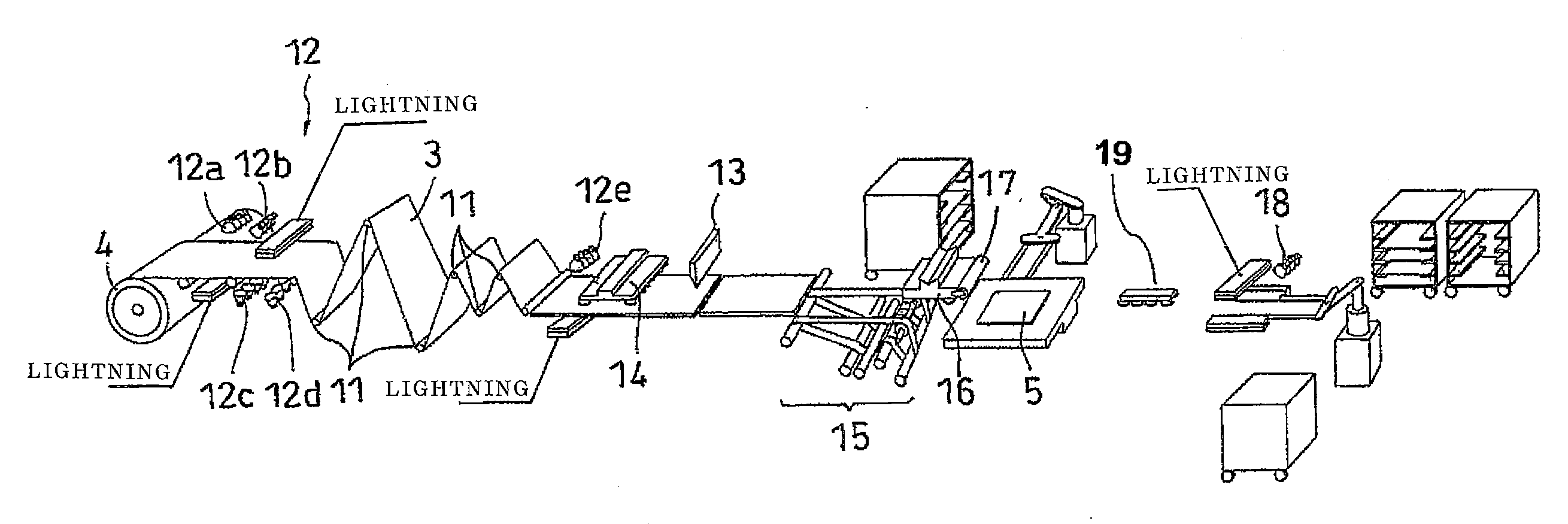
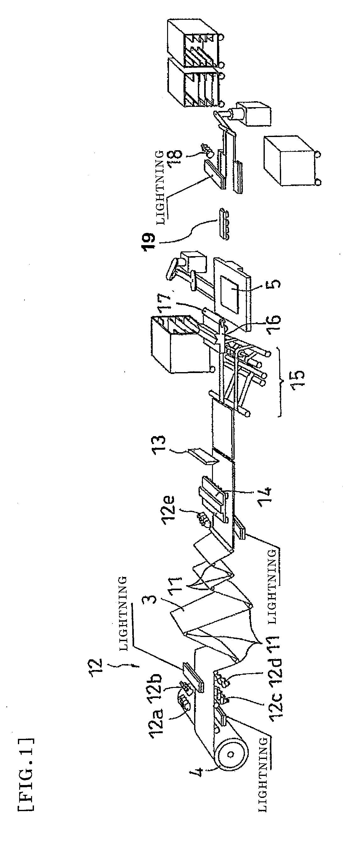
[0026]Preferred embodiments of the invention are described below. Sheet-Shaped Product, Optical Display Unit and Optical Display

[0027]A description is given of some embodiments using a raw polarizing plate as an example of the sheet-shaped product to be handled according to the invention. The raw polarizing plate is in the form of a long film, and polarizing plates each with a specific size are punched (or cut) from the film-shaped raw polarizing plate. For example, the raw polarizing plate may be produced by sticking a triacetylcellulose film (transparent protective film) to both the front and back sides of a previously prepared polyvinyl alcohol film (polarizer). It is necessary to detect whether or not defects (such as scratches and foreign matter) are present on the surface of or in the interior of the raw polarizing plate with such a multilayer structure. The defects are detected by the detection means described later.

[0028]The raw polarizing plate may be produced by a manufact...


PUM

PropertyMeasurementUnit
thicknessaaaaaaaaaa
thicknessaaaaaaaaaa
thicknessaaaaaaaaaa

Abstract

An object of the invention is to provide an optical display manufacturing system or method that allows an increase in the yield of an optical film, a reduction in cost and an improvement in inventory control. An optical display manufacturing system includes feeding means (11, 14) that feeds a belt and sheet-shaped product (3) having an optical film from a roll (4) of the belt and sheet-shaped product, detection means (12) that detects a defect of the belt and sheet-shaped product fed by the feeding means, cutting means (13) that cuts the belt and sheet-shaped product into individual sheet-shaped products based on the result of the detection, transfer means (16) that transports each of the sheet-shaped products from the cutting process to a sticking process, and sticking means (17) that sticks the transported sheet-shaped product to an optical display unit.

Description

TECHNICAL FIELD[0001]The invention relates to systems and methods for manufacturing optical displays. More specifically, the invention relates to a system and method for manufacturing an optical display including a laminate of a belt- or sheet-shaped product and an optical display unit.BACKGROUND ART[0002]According to conventional techniques, optical film makers manufacture a roll of a belt and sheet-shaped product having an optical film component in a continuous manner. Examples of the “belt and sheet-shaped product” include a raw polarizing plate, a raw retardation plate, and a raw laminated film of a polarizing plate and a retardation plate each for use in liquid crystal displays. The optical film component is supplied to panel makers who assemble the optical film component (such as a polarizing plate and a retardation plate) and an optical display unit (such as a sealed glass substrate unit containing a liquid crystal cell) from the optical film makers. The optical film makers p...

Claims


Application Information

Patent Timeline
Patent Type & Authority Applications(United States)
IPC IPC(8): B32B37/00B32B38/00
CPCB32B37/182B32B38/0004B32B41/00B32B2038/042B32B2457/202G02F1/1303Y10T156/12Y10T156/1084Y10T156/1056Y10T156/1052Y10T156/1057Y10T156/1062G02F1/133528G02F1/13G02F1/1335G09F9/00
Inventor NAKAHIRA, YASUSHIABE, HIDEO
Owner NITTO DENKO CORP
Why Eureka
Try Eureka