
Vehicle air-conditioning system

a technology for air-conditioning systems and vehicles, applied in the direction of machines, light and heating equipment, transportation and packaging, etc., can solve the problems of in-car temperature fluctuation due to temperature fluctuation, discomfort felt by the occupant in the vicinity, etc., to suppress the immediate fluctuation of in-car temperature, suppress the immediate fluctuation of blowing temperature, and adjust the ability of air-conditioning.

Inactive Publication Date: 2009-06-25
MITSUBISHI ELECTRIC CORP
View PDF2 Cites 5 Cited by
  • Summary
  • Abstract
  • Description
  • Claims
  • Application Information

AI Technical Summary

Benefits of technology

The present invention proposes a vehicle air-conditioning system that can further reduce temperature fluctuation of blowing-out air compared to a hitherto known system. The system includes a cooling apparatus and a heating apparatus capable of changing an amount of withdrawn heat and generated heat in a stepwise manner, and a control device that calculates an amount of heat to be supplied to a car interior and sets the supplying amount of heat of the cooling and heating apparatus accordingly. The system can suppress immediate fluctuation of in-car temperature and improve the product life duration of switches.

Problems solved by technology

As described above, in a hitherto known vehicle air-conditioning system, since a required air-conditioning capability is generated in an approximate manner by means of operation of a compressor in a stepwise manner in combination with a turning-on rate control of a heater, there has been a problem that an in-car temperature fluctuates due to temperature fluctuation of blowing-out air caused by repetition of turning-on and turning-off operations of the heater.
Further, there has been another problem that a sense of discomfort is felt by an occupant in the vicinity of a blowing-outlet due to the temperature fluctuation (temperature ripple) of the blowing-out wind.

Method used


Image

  • Vehicle air-conditioning system
  • Vehicle air-conditioning system
  • Vehicle air-conditioning system

Examples


Embodiment Construction

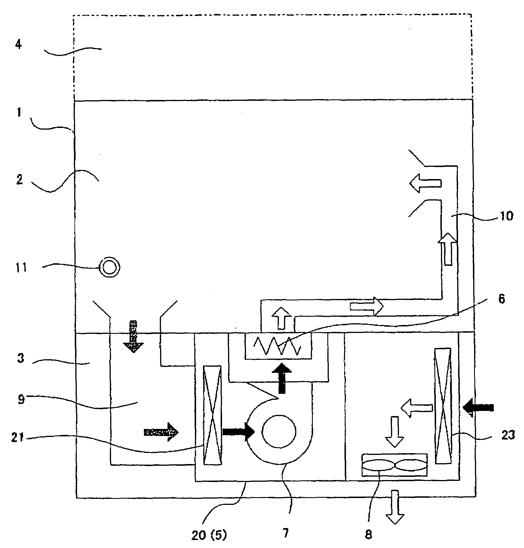
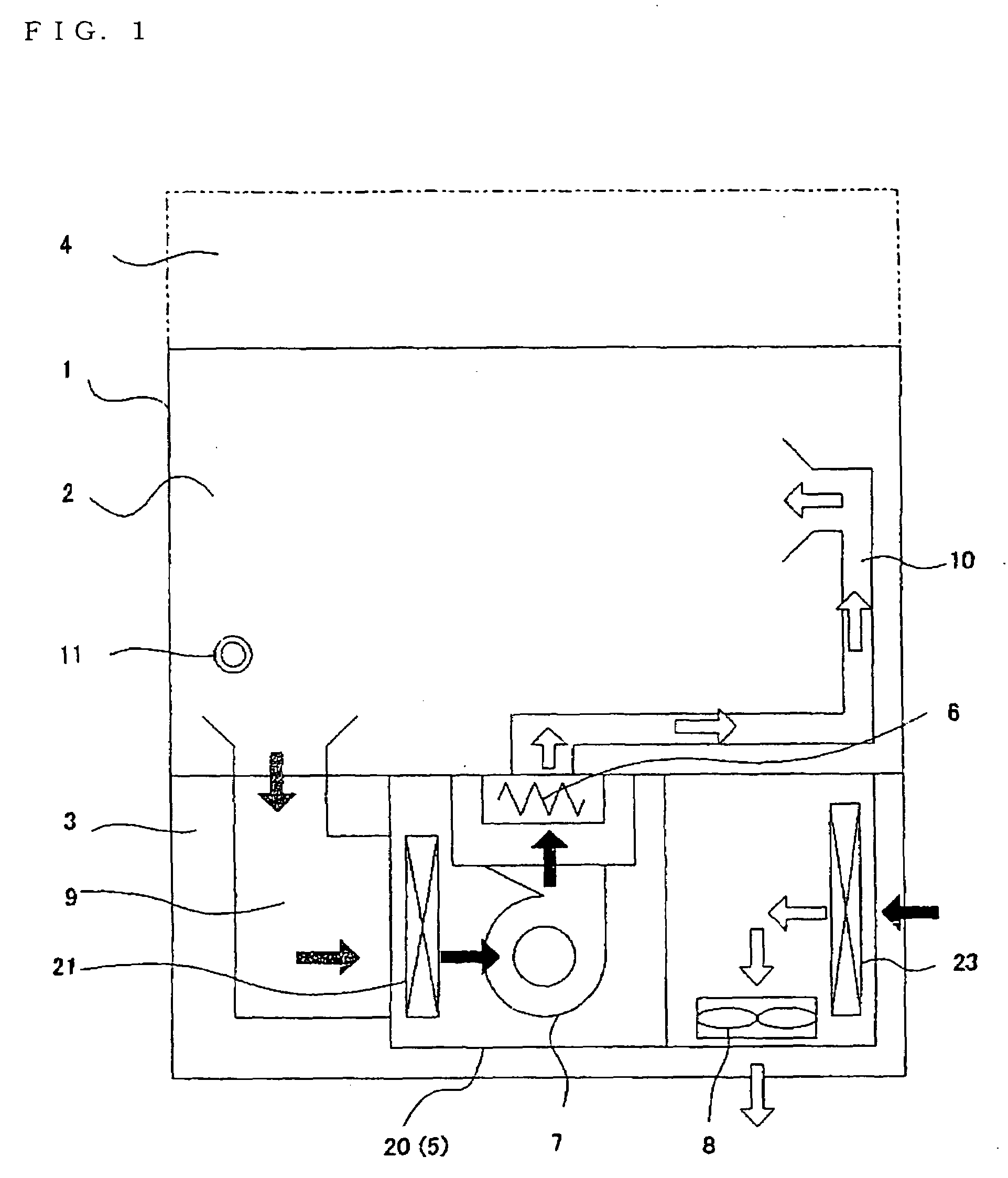
[0018]FIG. 1 is a construction view of a vehicle air-conditioning system with respect to the embodiment of the present invention. In FIG. 1, a vehicle 1 in which an air-conditioning system 20 is installed is configured to be composed of an in-car space (sometimes also called car interior, simply) 2, an under floor space 3, and an above-the-roof space 4. Incidentally, although a case that the air-conditioning system 20 is installed in the under floor space 3 is described in FIG. 1, there is also a case that the air-conditioning system 20 is installed in the above-the-roof space 4. The air-conditioning system 20 is provided with a cooling apparatus 5 that is capable of changing an amount of withdrawn heat in a stepwise manner, a heating apparatus 6 capable of changing an amount of generated heat in a stepwise manner, an indoor fan 7, and an outdoor fan 8.

[0019]Incidentally, a numeral 9 in FIG. 1 denotes a returning duct that returns air from the in-car space 2 to the air-conditioning ...


PUM


Abstract

To propose a vehicle air-conditioning system capable of further reducing a temperature fluctuation of blowing-out air when temperature-conditioned air is supplied to an in-car space.The vehicle air-conditioning system including a cooling apparatus 5 capable of changing an amount of withdrawn heat in a stepwise manner, heaters 6A, 6B, and 6C, each having different heat release capability, which constitutes a heating apparatus 6 capable of changing an amount of generated heat in a stepwise manner, and a control device 30 including a supplying amount of heat calculating portion 30A for calculating a supplying amount of heat to an in-car space 2 and an amount of generated and withdrawn heat setting portion 30B for setting amounts of withdrawn and generated heat of the cooling apparatus 5 and the heating apparatus 6 on the basis of the supplying amount of heat calculated by means of the supplying amount of heat calculating portion 30A.

Description

BACKGROUND OF THE INVENTION[0001]1. Field of the Invention[0002]The present invention relates to an air-conditioning system, and more particularly to an air-conditioning system for use in a vehicle.[0003]2. Related Arts[0004]A vehicle air-conditioning system utilizing a refrigeration cycle is already known (refer to, for example, patent documents, 1 and 2). In addition to the above, an automatic control for automatically adjusting the air-conditioning capability to conform an in-car temperature to a target temperature is recently performed. Although a controller (temperature controller) continuously requires the air-conditioning capability necessary for a deviation between the target temperature and the in-car temperature, the air-conditioning capability (cooling capability) cannot be changed in a manner other than a stepwise manner. This is because a compressor used for a cooling apparatus cannot perform operation other than that in a stepwise manner only at frequencies whose safet...

Claims


Application Information

Patent Timeline
Patent Type & Authority Applications(United States)
IPC IPC(8): B60H1/00F25B29/00
CPCB60H1/00807B60H1/00878F25B2600/021F25B2400/01F25B29/00B60H1/2218
Inventor ISODA, SHOJI
Owner MITSUBISHI ELECTRIC CORP
Learn More