Hydraulically actuable vehicle brake having a locking means

a technology of hydraulic actuator and locking means, which is applied in the direction of actuators, brake actuating mechanisms, friction linings, etc., can solve the problems of correspondingly powerful electromotive components and relative complexity of bulky mechanisms, and achieve the effect of ensuring the stability of components

Inactive Publication Date: 2009-06-25
MOHR KURT +1
View PDF13 Cites 6 Cited by
  • Summary
  • Abstract
  • Description
  • Claims
  • Application Information

AI Technical Summary

Benefits of technology

[0006]A problem of the present invention is to provide a vehicle brake of the initially described type that requires only low actuating forces to activate the parking brake function and guarantees a stable position of the components in a parking brake situation.

Problems solved by technology

However, this entails a relatively complicated bulky mechanism and correspondingly powerful electromotive components.

Method used


Image

  • Hydraulically actuable vehicle brake having a locking means
  • Hydraulically actuable vehicle brake having a locking means
  • Hydraulically actuable vehicle brake having a locking means

Examples


Embodiment Construction

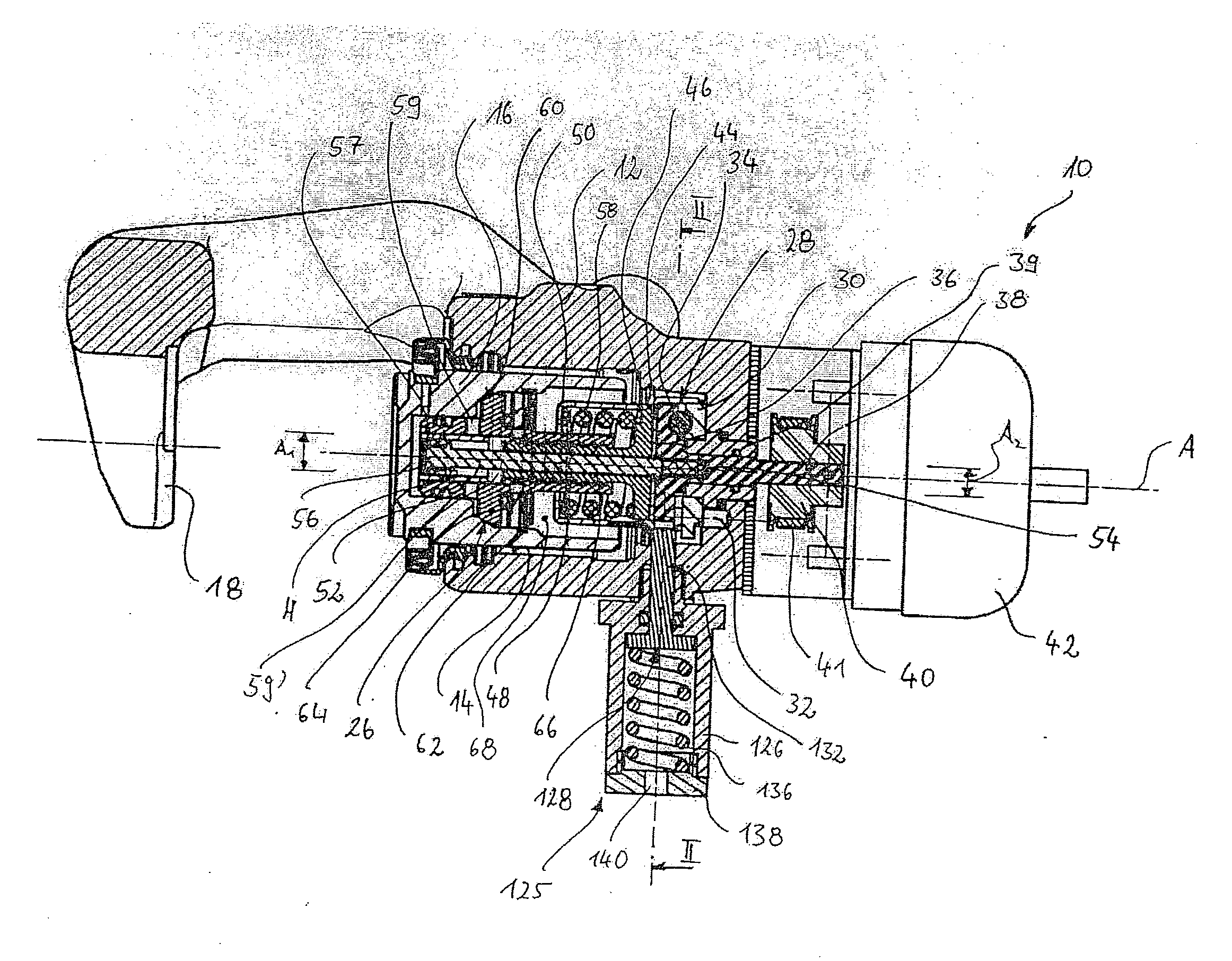
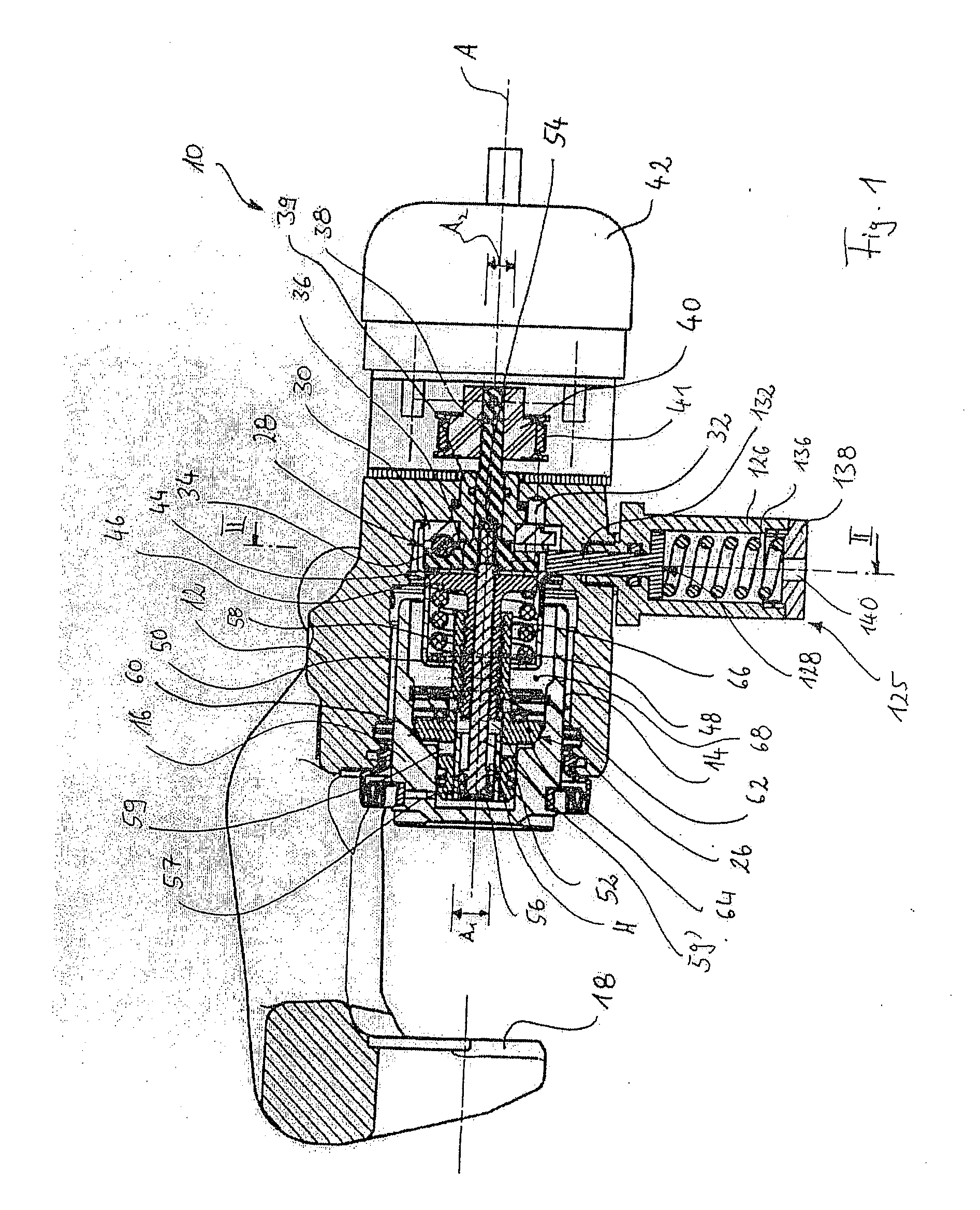
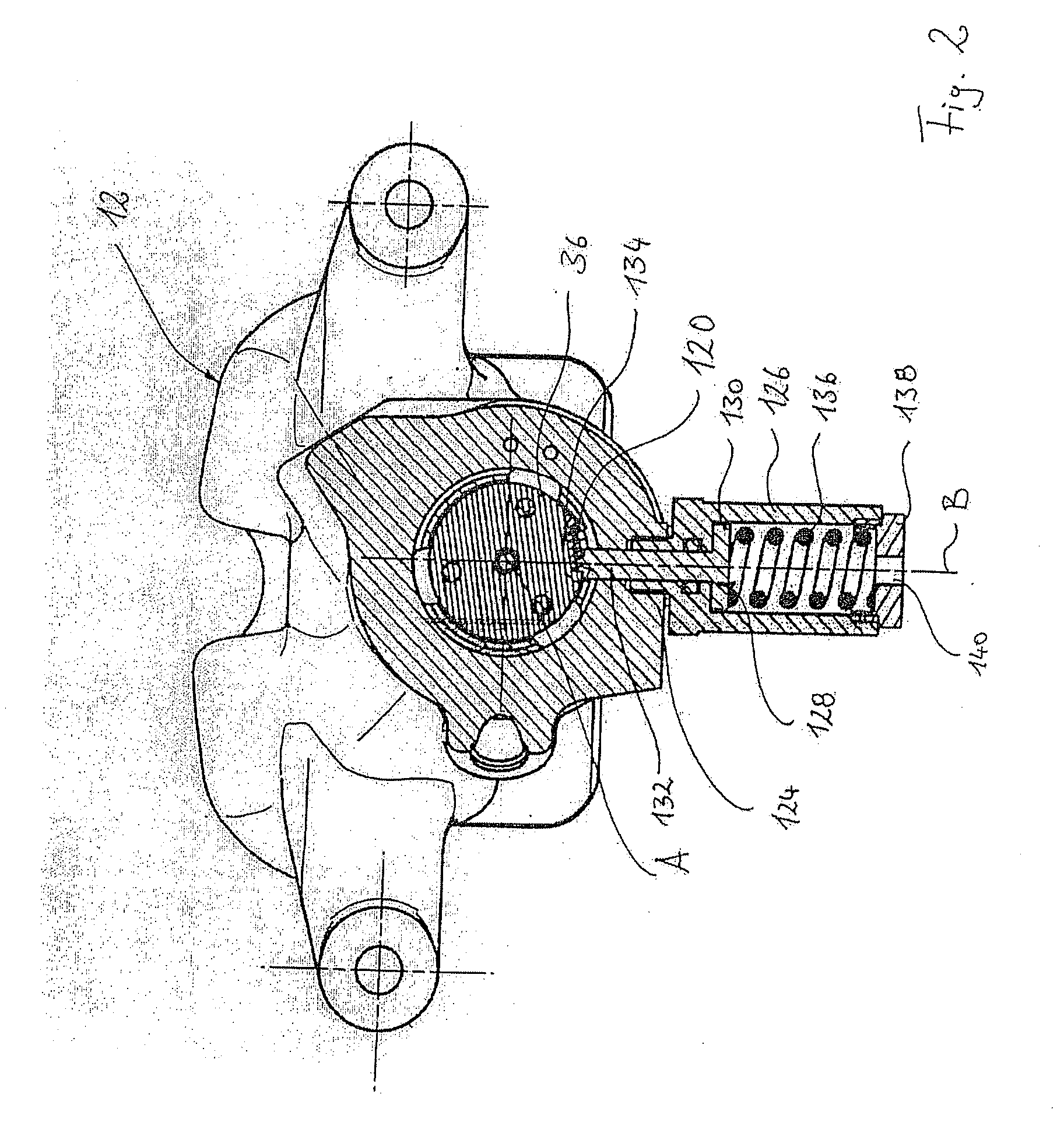
[0033]First, the first embodiment is described below with reference to FIGS. 1 and 2.

[0034]In FIG. 1 a vehicle brake according to the invention is generally denoted by 10. It is designed with a housing 12, which has a cylindrical opening 14. In the cylindrical opening 14 a brake piston 16 is accommodated displaceably in a fluid-proof manner. The brake piston 16 at its, in FIG. 1 left, end is mechanically connectable to a brake lining carrier (not shown), to which a brake lining is fastenable. Lying opposite the brake lining is a further brake lining, which is fastened to a housing part 18 lying opposite. The brake linings are accommodated in the housing 12 in a conventional manner based on the floating caliper principle.

[0035]The vehicle brake 10 further comprises a blocking device 26, by means of which the brake piston 16 may be arrested in various axial positions along the piston longitudinal axis A. The blocking device 26 in the first embodiment comprises a ramp arrangement 28 ha...


PUM


Abstract

The present invention relates to a vehicle brake (10) comprising a housing (12), a brake piston (16) accommodated in the housing (12) and coupled to a brake lining (20), a blocking device (26) for arresting the brake piston (16) inside the housing (12), and an electromechanical actuating device (42) for activating the blocking device (26) in a parking brake situation, wherein the brake piston (16) together with the housing (12) delimits a fluid chamber (68) that is chargeable with hydraulic fluid, so that the brake piston (16) for actuating the vehicle brake (10) is hydraulically displaceable inside the housing (12) along a piston longitudinal axis (A). In such a vehicle brake it is provided that there is associated with the blocking device (26) a locking arrangement (125), which in a parking brake situation acts mechanically on a component (36) of the blocking device (26) and locks the blocking device against a resetting movement.

Description

CROSS-REFERENCE TO RELATED APPLICATIONS[0001]This application claims priority to International Patent Application No. PCT / EP2007 / 003008 filed Apr. 3, 2007, the disclosures of which are incorporated herein by reference in entirety, and which claimed priority to German Patent Application No. 10 2006 016 543.8 filed Apr. 7, 2006, the disclosures of which are incorporated herein by reference in entirety.BACKGROUND OF THE INVENTION[0002]The present invention relates to a hydraulically actuable vehicle brake comprising a housing, a brake piston accommodated in the housing and coupled to a brake lining, a blocking device for arresting the brake piston inside the housing, and an electromechanical actuating device for activating the blocking device in a parking brake situation, wherein the brake piston together with the housing delimits a fluid chamber that is chargeable with hydraulic fluid so that the brake piston for actuating the vehicle brake is hydraulically displaceable inside the hou...

Claims


Application Information

Patent Timeline
Patent Type & Authority Applications(United States)
IPC IPC(8): F16D65/14
CPCF16D65/18F16D2121/02F16D2125/36F16D2129/10F16D2127/06F16D2129/02F16D2125/44
Inventor MOHR, KURTSCHMITZ, MANUEL
Owner MOHR KURT
Why Eureka
Try Eureka