Plasma Display panel and plasma display

a technology of display panel and plasma display, which is applied in the direction of electrical discharge tubes, auxillary electrodes, instruments, etc., can solve the problems of uneven luminance, inability to delay the discharge timing, and the voltage drop at the electrode becomes a problem, so as to prevent the luminance from lowering and increase the color temperature of white

Inactive Publication Date: 2009-06-25
FUJITSU HITACHI PLASMA DISPLAY LTD
View PDF6 Cites 2 Cited by
  • Summary
  • Abstract
  • Description
  • Claims
  • Application Information

AI Technical Summary

Benefits of technology

[0008]According to the technique of Patent Document 2, it is possible to increase the color temperature of white by changing the widths of the X, Y electrodes per color. However, since the interval between the X, Y electrodes is fixed, it is not possible to delay the discharge timing.
[0009]The present invention was made in consideration of the above problems in the prior art. Accordingly, an object of the present invention is to provide a technique in the techniques of 4-electrode PDP, PDP module, plasma display apparatus and the like for easing the concentration of the discharge timing so that preventing the luminance lowering depending on the display load ratio due to the voltage drop in the electrodes.
[0013]According to the structure of the present PDP, in the case where a voltage for sustain discharge driving is applied to the plurality of cells having these different intervals (XZ, YZ) from the driver side, since the intervals (XZ, YZ) are different in the respective cells in the structure, firing voltages differ therebetween, and firing timing is distributed bit by bit. Therefore, such the concentration of discharge timing as in the prior art is eased and accordingly the increase of the current to instantaneously flow in the electrodes is eased and the voltage drop is controlled and reduced. Consequently, it is possible to cope with the luminance lowering depending on the display load ratio dependence due to the voltage drop, and to prevent uneven luminance in the plurality of cells. More details are described below.
[0022]The effects obtained by typical aspects of the present invention will be briefly described below. According to the present invention, in the 4-electrode PDP, it is possible to distribute discharge timing of respective cells particularly in a sustain discharge, so that the luminance lowering due to the voltage drop is eased and prevented. Therefore, it is possible to keep the luminance of the respective cells roughly constant irrespective of the display load ratio, i.e., it is possible to prevent uneven luminance.

Problems solved by technology

In the PDPs, luminance lowering depending on the display load ratio due to voltage drop at electrodes becomes a problem.
In particular, when the display load ratio is large, the amount of voltage drop becomes large and it leads to uneven luminance.
However, since the interval between the X, Y electrodes is fixed, it is not possible to delay the discharge timing.

Method used


Image

  • Plasma Display panel and plasma display
  • Plasma Display panel and plasma display
  • Plasma Display panel and plasma display

Examples


first embodiment

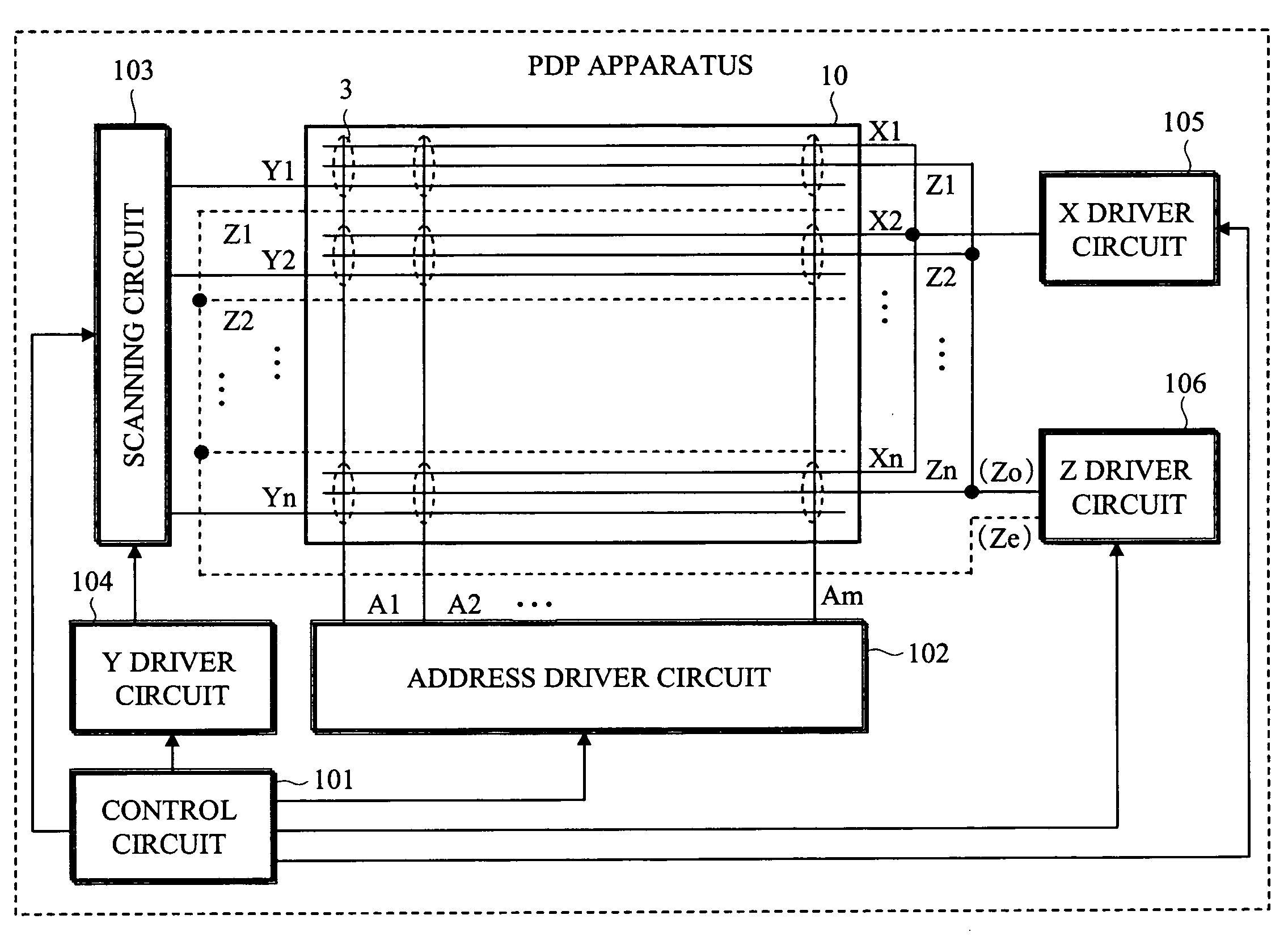
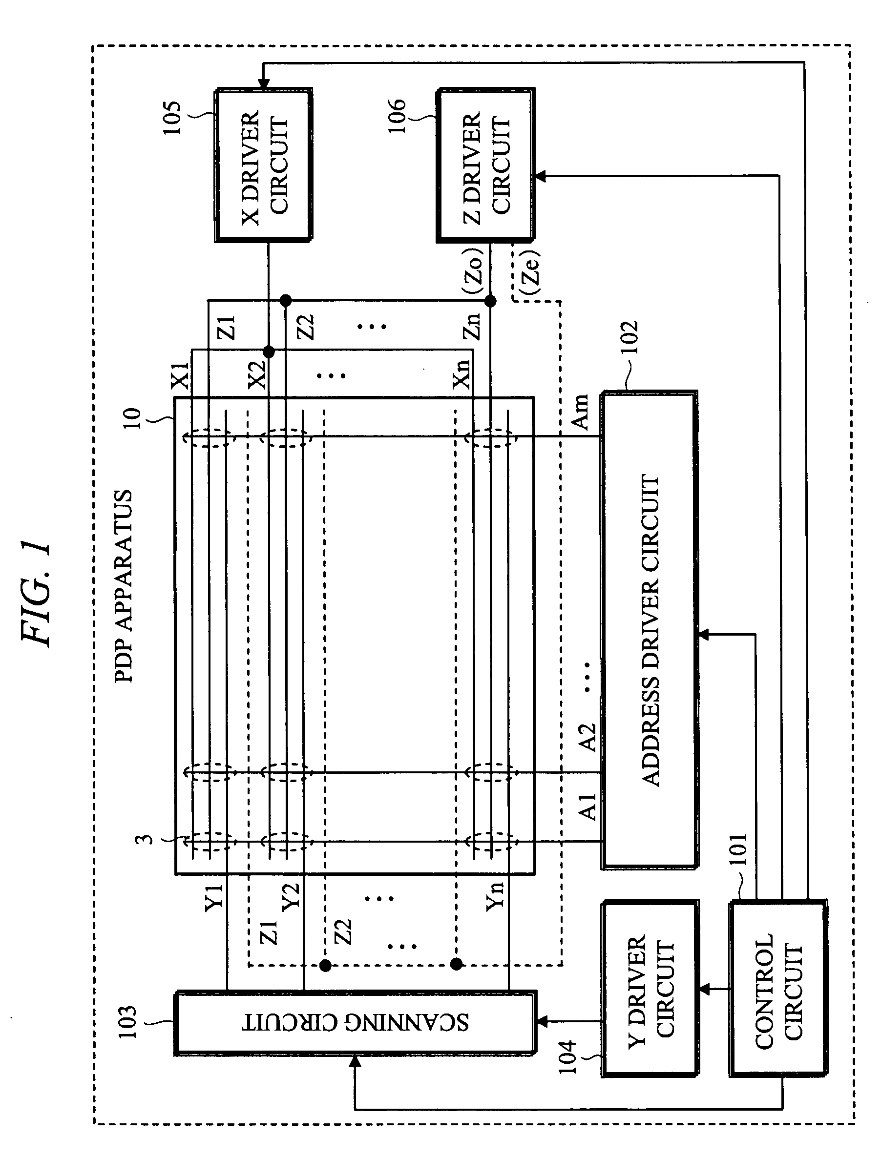
[0033]The outline of a PDP apparatus according to a first embodiment is as described below. In a structure of a PDP having first (X), second (Y), third (Z), fourth (A) electrodes, respective bus electrodes of X, Y, Z are arranged roughly in parallel in a straight line shape, discharge electrodes of X, Y are made into a same shape, and the shape of a discharge electrode of the Z electrode is made different. Per cells of the respective colors of R, G, B which are adjacent in a lateral direction (first direction), intervals (XZ, YZ) between the Z electrode and the X, Y electrodes, in particular, distances between edges of the respective discharge electrodes are made different. In particular, among R, G, B, the intervals (XZ, YZ) in R are made narrow, and the intervals (XZ, YZ) in B are made wide. In other words, it is a configuration where a firing voltage for a sustain discharge is higher in the order of R, G, B. In particular, in the first embodiment, the shape of the discharge elect...

second embodiment

[0090]Next, as the other embodiment according to the present invention, a second embodiment is described. The outline of a PDP apparatus of the second embodiment is as describe below. The second embodiment has a structure having Z electrodes whose shape is different from that of the first embodiment. In the second embodiment, the shape of discharge electrode of the Z electrode per cell is made into a rectangular triangle, that is, a shape where a specified angle is made by a line (first direction) of bus electrode and an edge of an opposing electrode. In the line (first direction) of the bus electrode, there is formed a saw-teeth shape where a pattern of protruding portions of rectangular triangles in different sizes is arranged.

[0091]FIG. 9 shows the structure of the cells 3 of the PDP 10 in the second embodiment in the same manner as in FIG. 3. In the second embodiment, the shapes of Z discharge electrodes 25 {25r, 25g, 25b} (positive slit side), 26 {26r, 26g, 26b} (reverse slit s...


PUM


Abstract

A technology for the four-electrode type PDP for preventing the lowering of luminance depending on the display load ratio due to the voltage drop at electrode by mitigating concentration of discharge timing. On a front substrate of a PDP (10), a first (X) electrode, a second (Y) electrode, and a third (Z) electrode therebetween are arranged in parallel in a first direction. Between Substrates, barrier ribs for sectioning cells 3 of respective colors of R, G, B and phosphor layers of respective colors are provided. In the respective cells (3), an interval of the X, Y electrodes is roughly constant. It is a structure where intervals between the X, Y electrodes and the Z electrode (XZ, YZ) are different. Particularly, an interval of R is narrow and an interval of B is wide.

Description

TECHNICAL FIELD[0001]The present invention relates to a technique relating to a display panel and driving for various applications, such as display devises for personal computers and work stations and the like, flat wall-hanging TV sets, and displays for advertisement and information and the like. More particularly, the present invention relates to a technique of an AC type plasma display panel (hereinafter, abbreviated as PDP), a PDP module structured by including the PDP and a driver circuit and the like, and a PDP apparatus (plasma display device) including the PDP module.BACKGROUND ART[0002]In recent years, 3-electrode PDPs have been widely used. The 3-electrode PDP generally has a structure where X electrodes and Y electrodes are arranged in parallel alternately in a first direction on a first substrate, address electrodes which expand so as to cross in a direction vertical to the X, Y electrodes in the first direction are arranged on a second substrate opposing the first subst...

Claims


Application Information

Patent Timeline
Patent Type & Authority Applications(United States)
IPC IPC(8): G09G3/28G09G3/288G09G3/298H01J11/12H01J11/24H01J11/28H01J11/32
CPCG09G3/2986G09G2320/0223H01J11/12H01J2211/323H01J11/28H01J11/32H01J2211/245H01J11/24
Inventor KOBAYASHI, TAKAYUKISASAKI, TAKASHIITOKAWA, NAOKITERAOKA, TOORU
Owner FUJITSU HITACHI PLASMA DISPLAY LTD
Why Eureka
Try Eureka