Transmitter-receiver

a technology of transmitter and receiver, applied in the direction of electrical equipment, digital transmission, radio transmission, etc., can solve the problems of power amplifier on the transmission side, inability to operate the transmission amplifier in a satisfactory state, and increased cos

Inactive Publication Date: 2009-06-25
FUJITSU LTD
View PDF6 Cites 20 Cited by
  • Summary
  • Abstract
  • Description
  • Claims
  • Application Information

AI Technical Summary

Benefits of technology

[0007]It is an object of the present invention to provide a transmitter receiver apparatus capable of operating the transmission amplifier in a satisfactory state. It is another object of the present invention to provide a transmitter receiver apparatus allowing a cost reduction.
[0010]According to this transmitter-receiver, by providing the directional coupler terminated in a predetermined impedance and balance type switches on the reception side, reflecting waves are canceled in the directional coupler during transmission, so that the load as viewed from the transmission side can always be shown as a predetermined impedance. Furthermore, by the reception signal being split into two signals, the ability required of the SPDT switches, to block the sneaking of the transmission power is allowed to be low, which enables the switches to be constituted by compact elements.

Problems solved by technology

However, when performing radio communications using a microwave band or a millimeter wave band, the transmitter-receiver disclosed in the above-described patent document involves the following problems.
As a result, reflection occurs in the switch circuit during the transmission, thereby raising a problem that the power amplifier on the transmission side, i.e., transmission amplifier cannot be operated in a satisfactory state.
Secondly, in the recent years, with an increasing trend of transmission power, transmission power sneaking into the reception side is on an upward trend.
It is therefore necessary to constitute the switch circuit by a large size element, resulting in an occurrence of a cost increase problem.

Method used


Image

  • Transmitter-receiver
  • Transmitter-receiver
  • Transmitter-receiver

Examples


first embodiment

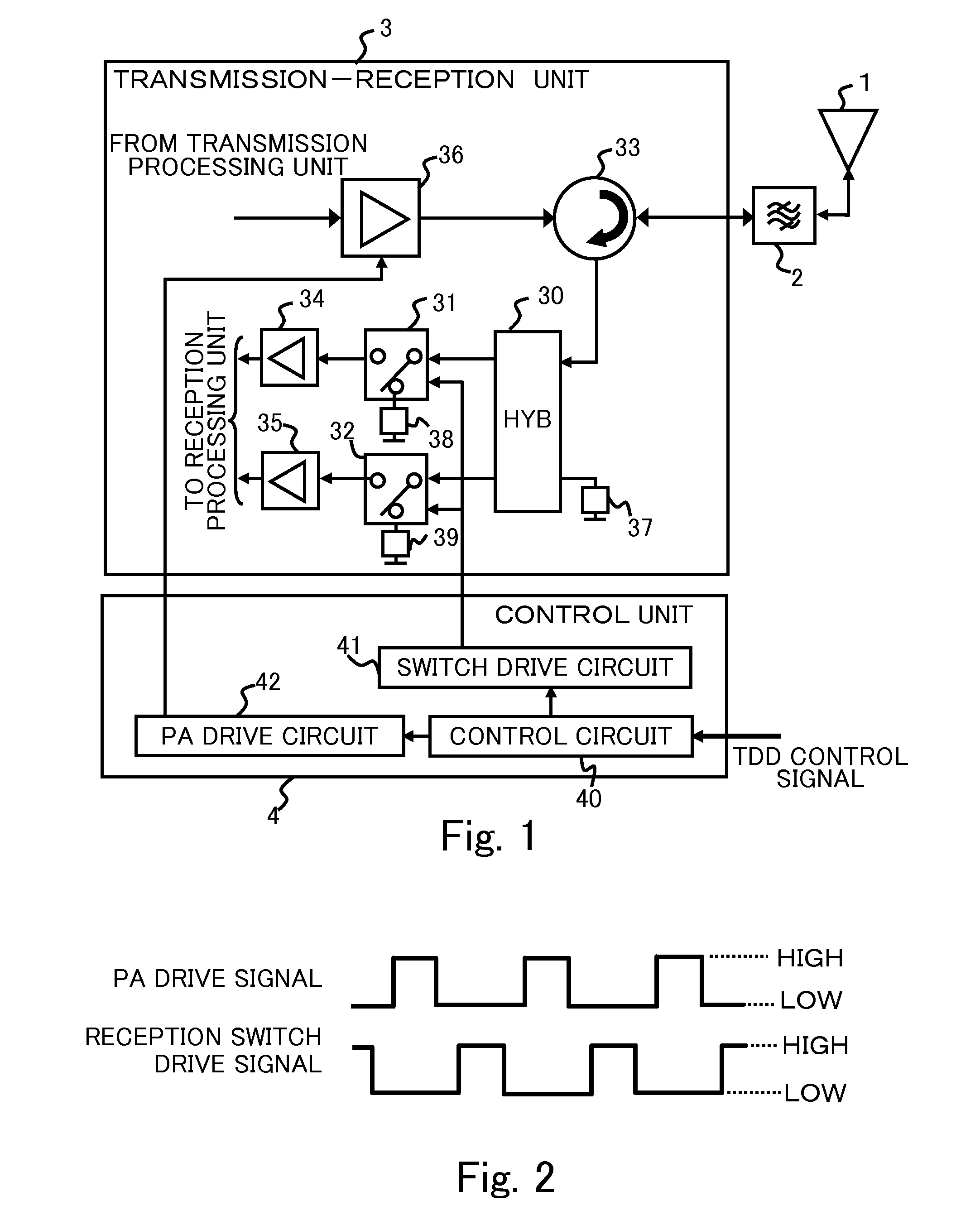
[0026]As shown in FIG. 1, in the transmission-reception unit 3, the transmitter-receiver includes the first directional coupler 30, the first SPDT switch 31, the second SPDT switch 32, a circulator 33 having a function as a transmission / reception switching circuit, a first low noise amplifier 34 having a function as a first reception amplifier, a second low noise amplifier 35 having a function as a second reception amplifier, an large power amplifier 36 having a function as a transmission amplifier. The circulator 33 includes a port for antenna, a port for reception, and a port for transmission.

[0027]The port for antenna is connected to the antenna 1, or connected to the band pass filter 2 when the band pass filter 2 is provided between the transmission-reception unit 3 and the antenna 1. The port for reception is connected to the first port of the first directional coupler 30. The port for transmission is connected to an output terminal of the large power amplifier 36. An input ter...

second embodiment

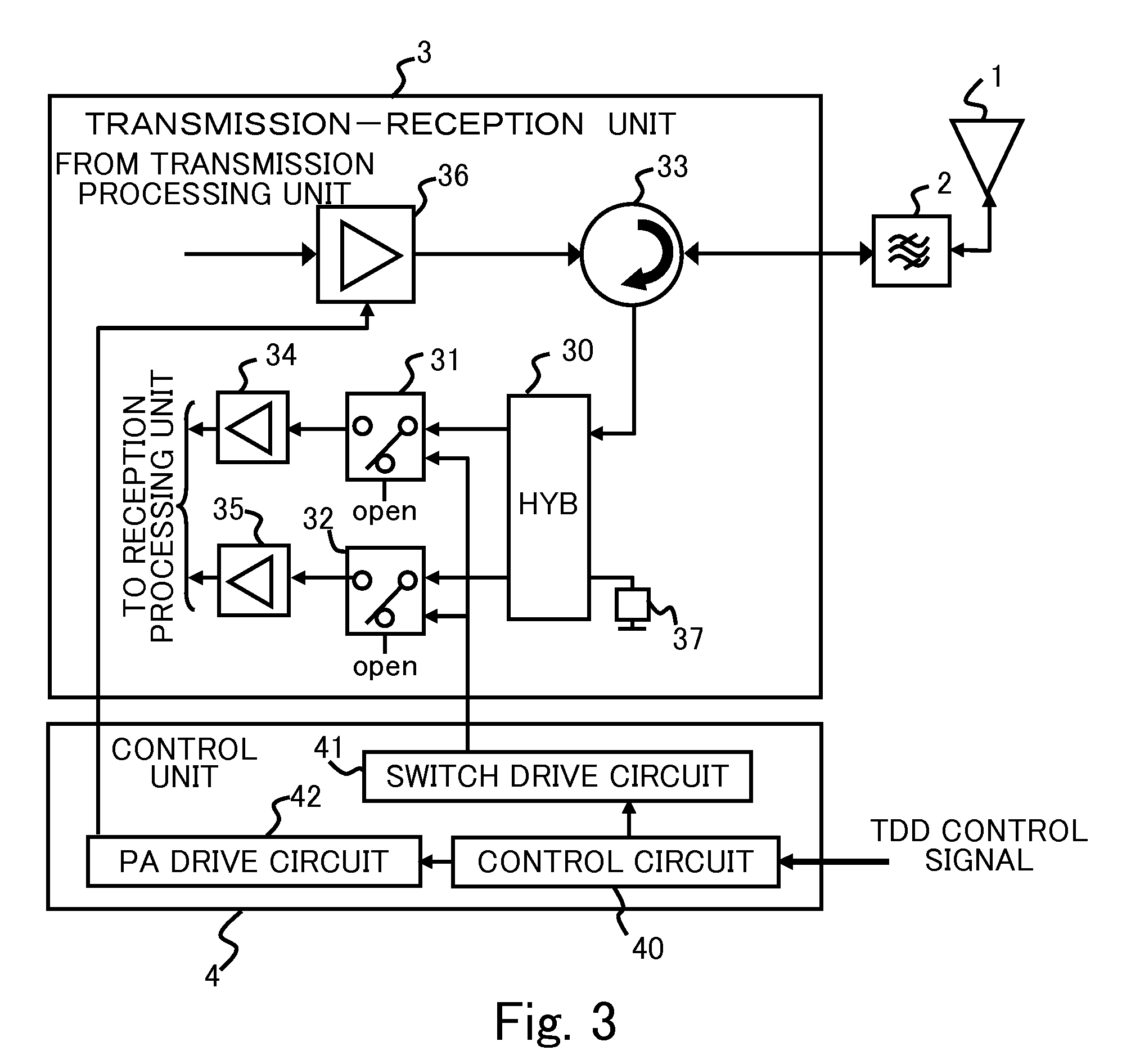
[0045]FIG. 3 is a block diagram showing a construction of a transmitter receiver apparatus according to a second embodiment. As shown in FIG. 3, in the transmitter-receiver, the second output terminal of the first SPDT switch 31 is in an opened state, and the fourth output terminal of the second SPDT switch 32 is in an opened state. The rests of the construction and the operations is the same as those of the first embodiment. In this way, even though the second output terminal of the first SPDT switch 31, and the fourth output terminal of the second SPDT switch 32 are not connected to the terminator of 50Ω, reflecting waves from the first SPDT switch 31 or the second SPDT switch 32 are cancelled in the first directional coupler 30 during transmission, the load as viewed from the transmission side is always 50Ω.

third embodiment

[0046]FIG. 4 is a block diagram showing a construction of a transmitter receiver apparatus according to a third embodiment. As shown in FIG. 4, the transmitter-receiver includes a second directional coupler 50, an in-phase combining circuit 51, and a VSWR detection circuit 52, and is operable to detect a voltage standing wave ratio (VSWR), using the output power of the large power amplifier 36 as forward power. The second directional coupler 50 is connected to the output terminal of the large power amplifier 36. The second directional coupler 50 is constituted, for example, by a coupler connected to the terminator 53 of 500Ω, and is operable to take out a part of a transmission signal outputted from the large power amplifier 36.

[0047]The in-phase combining circuit 51 is connected to the second output terminal of the first SPDT switch 31 and the fourth output terminal of the second SPDT switch 32. The in-phase combining circuit 51 combines two signals inputted from the first SPDT swi...


PUM


Abstract

There is provided a transmitter receiver apparatus in which a directional coupler and single pole double throw (SPDT) switches are includes on the reception side. In the directional coupler, a reception signal is inputted and split into two signals having phases different from each other by 90° and the two split signals are outputted to SPDTs. Each of the SPDTs outputs each of the split signals to an output terminal connected to an amplifier during a passage mode and to a terminal terminated with a predetermined impedance during a blocking mode.

Description

BACKGROUND[0001]1. Field[0002]The present invention relates to a transmitter receiver apparatus of a time division duplex (TDD) system, which performs transmission and reception in a time division manner.[0003]2. Description of the Related Art[0004]As a transmitter-receiver in the TDD system, there has hitherto been known one having a construction wherein a switch circuit that is in an ON state for a period of a reception slot is provided in a pre-stage of a reception circuit, and a circulator is connected between a transmission / reception antenna, and a transmission power amplifier and a switch circuit. In a technique described in Japanese Laid-Open Patent Publication 05-252074, for a period of a transmission slot, a transmission signal is supplied to the transmission / reception antenna from the power amplifier through the circulator. For the period of the reception slot, a reception signal received by the transmission / reception antenna is supplied to the reception circuit through th...

Claims


Application Information

Patent Timeline
Patent Type & Authority Applications(United States)
IPC IPC(8): H04L5/14H04B1/44
CPCH04B1/52H04B1/44
Inventor KASAI, MASAHIROYOKOYAMA, TAKASHIOKAWA, SHIGERU
Owner FUJITSU LTD
Why Eureka
Try Eureka