
Catheter

a catheter and distal end technology, applied in the field of catheters, can solve the problems of difficult navigation through narrow and/or tortuous body passageways, difficulty in frequently arising, and difficulty in advancing the catheter of the invention through a body passageway, so as to achieve high-speed catheter tracking, reduce resistance to advancement through body passageways, and maintain trackability

Inactive Publication Date: 2009-06-25
SALVIAC
View PDF3 Cites 1 Cited by
  • Summary
  • Abstract
  • Description
  • Claims
  • Application Information

AI Technical Summary

Benefits of technology

[0003]It is known to use a catheter to deliver and / or retrieve a medical device, such as an embolic protection filter, from a location in a body passageway. Body passageways are often narrow and / or tortuous due to the natural physiology of the patient, and / or due to diseased sections of the passageway. Thus difficulty frequently arises when attempting to navigate a catheter through such a body passageway. Skill is therefore required on the part of the clinician to prevent damage being caused to the passageway and / or discomfort to the patient during advancement of a catheter.
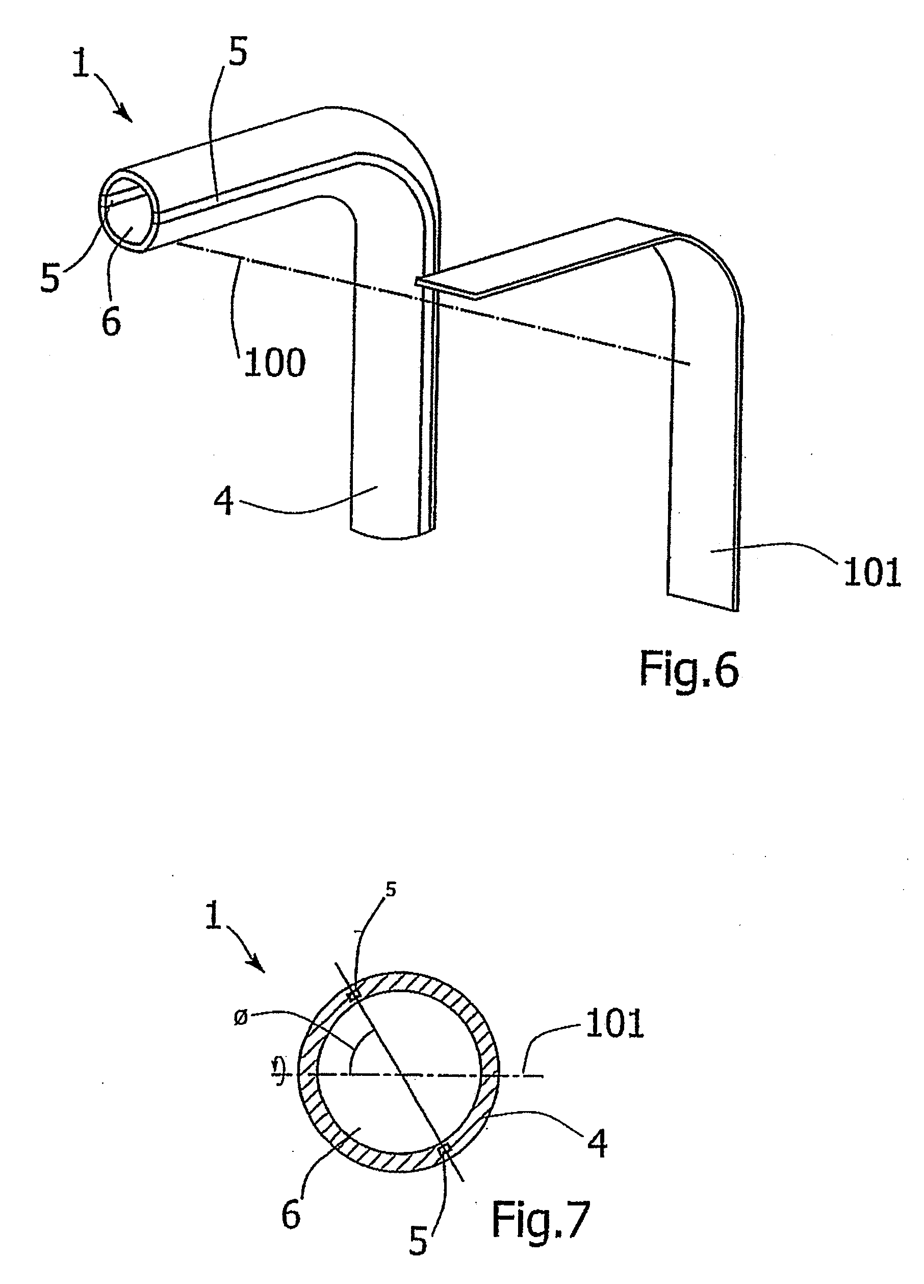
[0064]In a preferred arrangement the shape of the reinforcement may be configured to minimise the width of material perpendicular to the diameter running through the centre of the reinforcement. These shapes may however prove difficult to manufacture.

Problems solved by technology

Thus difficulty frequently arises when attempting to navigate a catheter through such a body passageway.
Furthermore, the distance that the catheter distal end travels through a passageway is often very long in comparison to the cross-sectional dimensions of the catheter.
Known attempts to achieve the required pushability have resulted in excessively stiff catheters which makes navigation through narrow and / or tortuous body passageways even more difficult.

Method used


Image

  • Catheter
  • Catheter
  • Catheter

Examples


Embodiment Construction

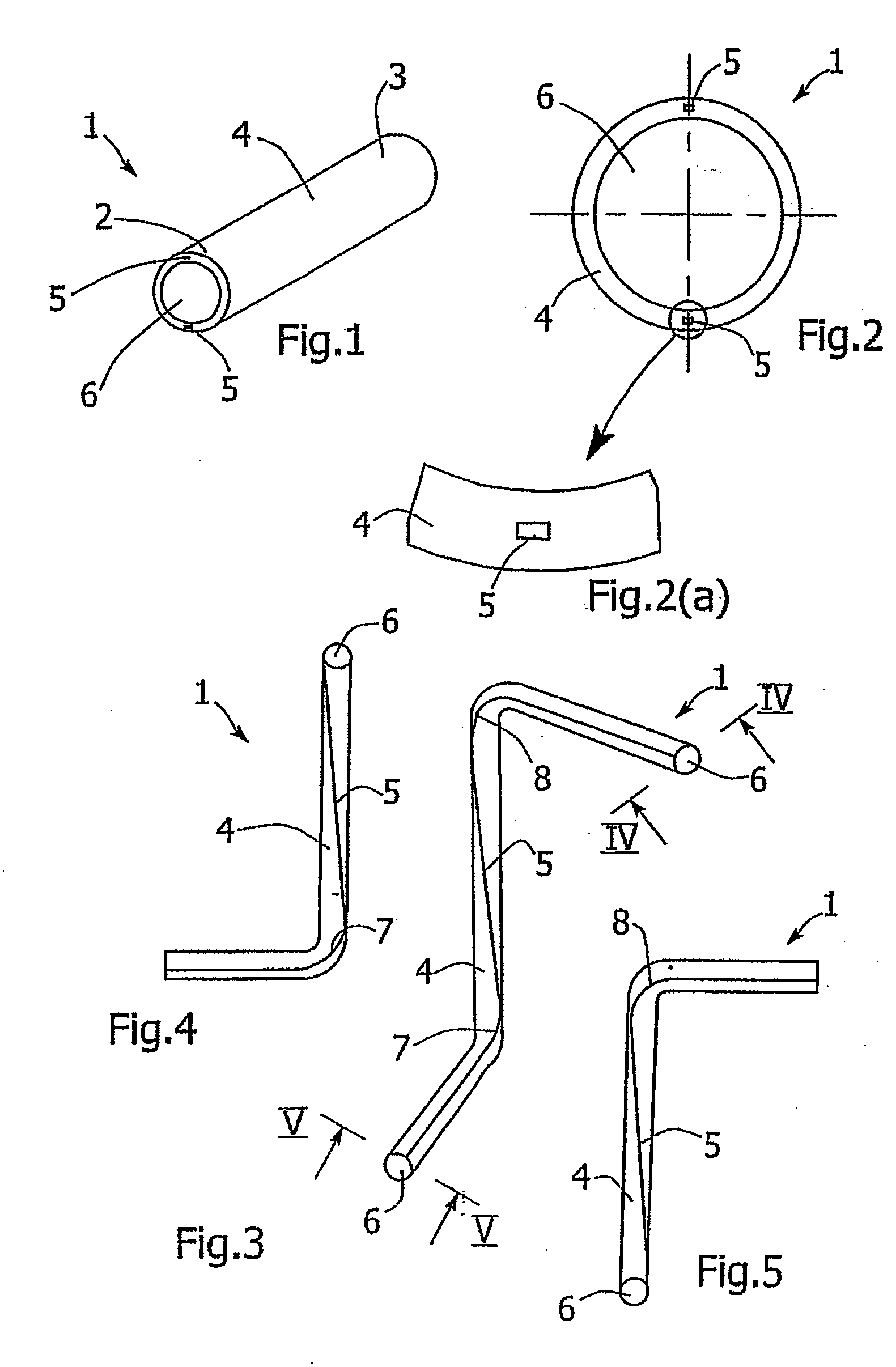
[0092]Referring to the drawings and initially to FIGS. 1 to 7 thereof, there is illustrated a catheter 1 according to the invention suitable for advancement through a body passageway of a patient.

[0093]The catheter 1 has a longitudinal axis, extends between a proximal end 2 and a distal end 3, and defines an inner lumen 6.

[0094]The catheter 1 comprises a catheter body 4 which is flexible to provide the necessary trackability for the catheter 1 to advance through a body passageway, and two reinforcements 5 extending along the catheter body 4 which provide the necessary pushability to advance the catheter 1 through the passageway.

[0095]The reinforcements 5 are fixed relative to the catheter body 4. In this case, the catheter body 4 is over-extruded over the reinforcements 5 to form the catheter 1, the reinforcements 5 being completely embedded within the catheter body 4 during the over-extrusion process for secure fixing of the reinforcements 5 within the catheter body 4 (FIG. 2(a)).

[...


PUM


Abstract

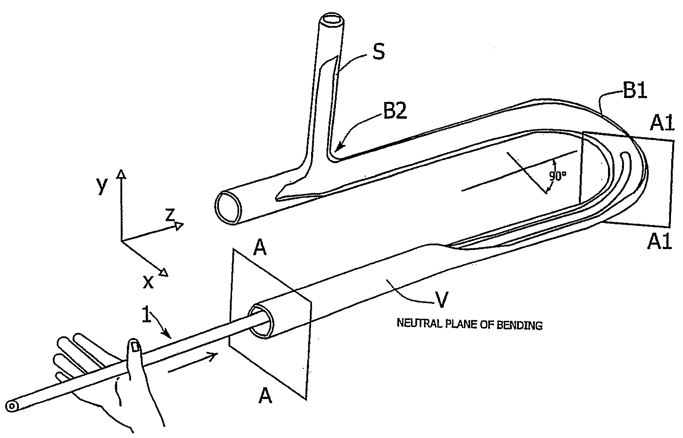
A catheter 1 suitable for advancement through a body passageway of a patient. The catheter 1 comprises a catheter body 4 which is flexible to provide the necessary trackability for the catheter 1 to advance through a body passageway, and two stainless steel reinforcement wires 5 extending along the catheter body 4 which provide the necessary pushability to advance the catheter 1 through the passageway. The reinforcements 5 are positioned diametrically opposed to one another by approximately 180 degrees on opposite sides of the longitudinal axis of the catheter 1, and the catheter body 4 is relatively soft and twistable. This configuration enables the entire catheter 1 to spontaneously twist during advancement so that the reinforcements 5 orientate themselves along a plane of neutral bending during advancement of the catheter 1. In this way, any resistance to the trackability of the catheter 1 due to the stiff reinforcements 5 is minimized.

Description

[0001]This application is a continuation of U.S. application Ser. No. 11 / 311,927 filed Dec. 19, 2005, which is a division of U.S. application Ser. No. 10 / 123,530 filed Apr. 17, 2002, which claims benefit of priority under 35 U.S.C. § 119 based on Ireland Patent Application No. 2001 / 0377 filed Apr. 17, 2001, and all of the disclosures of which are hereby incorporated by reference in their entirety.INTRODUCTION[0002]This invention relates to a catheter for advancement through a body passageway of a patient.[0003]It is known to use a catheter to deliver and / or retrieve a medical device, such as an embolic protection filter, from a location in a body passageway. Body passageways are often narrow and / or tortuous due to the natural physiology of the patient, and / or due to diseased sections of the passageway. Thus difficulty frequently arises when attempting to navigate a catheter through such a body passageway. Skill is therefore required on the part of the clinician to prevent damage bei...

Claims


Application Information

Patent Timeline
Patent Type & Authority Applications(United States)
IPC IPC(8): A61M25/00A61B17/22
CPCA61B17/22031A61B17/3439A61F2002/011A61M25/0068A61M25/005A61M25/0067A61M25/0043A61F2/011
Inventor CASEY, BRENDANO'HIGGINS, AVRILBRADY, EAMONGRIFFIN, PATRICK
Owner SALVIAC
Learn More