Method and apparatus for optimizing magnetic signals and detecting casing and resistivity

a magnetic signal and optimizing technology, applied in the field of well drilling operations, can solve the problems of increasing rig time and cost, significant and costly errors, and only getting periodic wellbore location information

Active Publication Date: 2009-06-25
SCHLUMBERGER TECH CORP
View PDF23 Cites 60 Cited by
  • Summary
  • Abstract
  • Description
  • Claims
  • Application Information

AI Technical Summary

Problems solved by technology

Conducting locating surveys utilizing wireline tools, and relying on those results, has significant drawbacks.
For example, using wireline equipment increases rig time and costs.
Further, wellbore location information is only obtained periodically with these wireline methods.
This unavailability to have constant, timely and accurate data can result in significant and costly errors.
If the weight of the drilling mud is too low, the formation pressure exceeds the borehole pressure and fluids from the formation enter the wellbore in an uncontrolled manner.
This is a serious situation that may endanger people and the environment and that may damage the drilling rig and the reservoir.
Eventually, the relief well is able to intercept the blow-out, but this may require a large number of trips, i.e., the drill string is removed and a wireline magnetic ranging tool is run into the open hole.
Each trip may require one or more days of rig time, so the process can be very slow and expensive.
The relief well has a very heavy mud that can “kill” the blow-out by reestablishing a borehole pressure greater than the formation pressure.
Cold pipelines increase the viscosity of the heavy oil and may prevent its production.

Method used


Image

  • Method and apparatus for optimizing magnetic signals and detecting casing and resistivity
  • Method and apparatus for optimizing magnetic signals and detecting casing and resistivity
  • Method and apparatus for optimizing magnetic signals and detecting casing and resistivity

Examples


Embodiment Construction

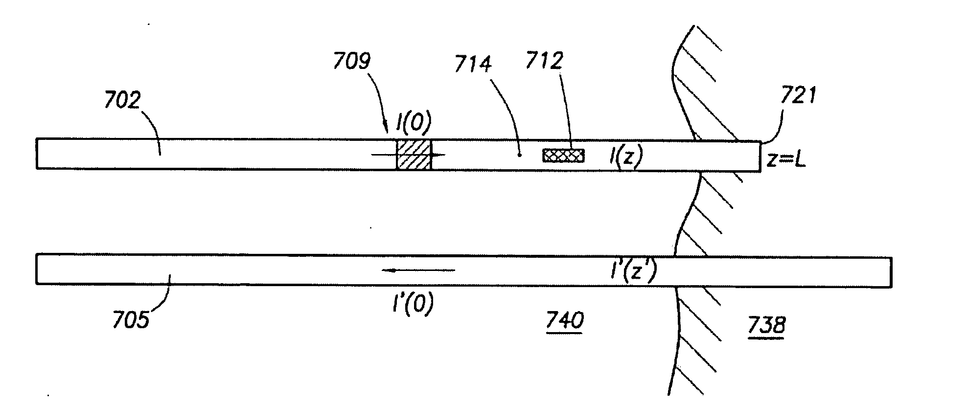
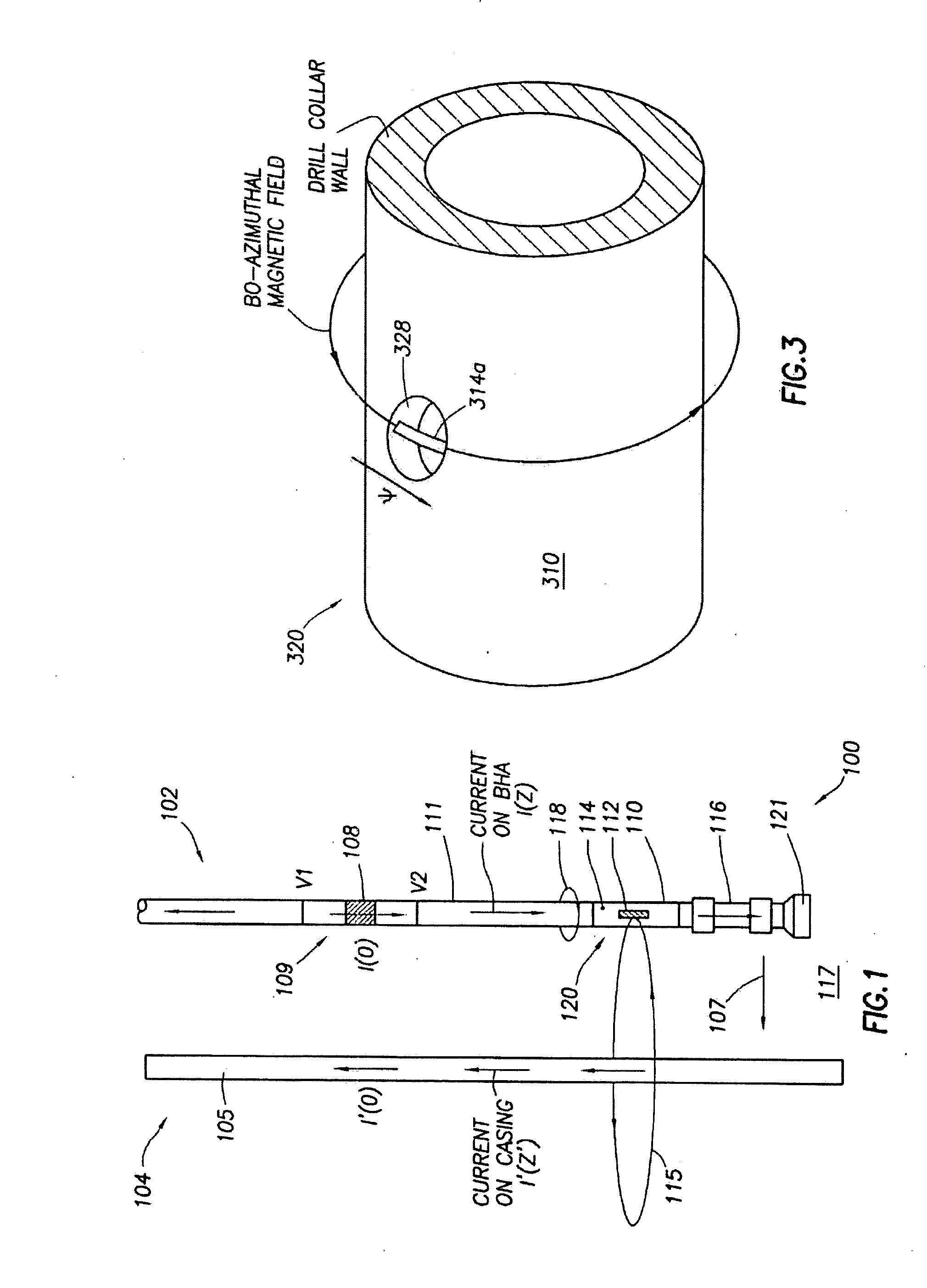
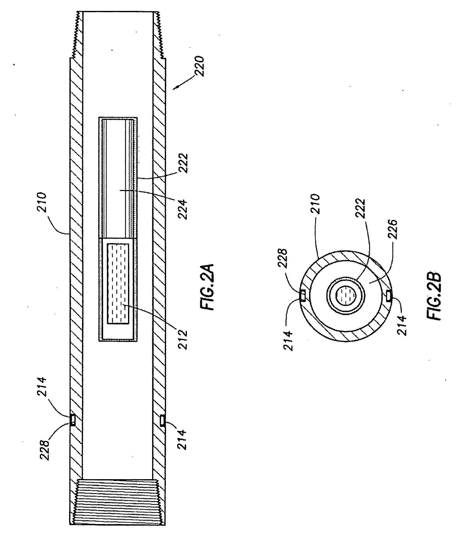
[0031]In one aspect, embodiments of the invention relate to well drilling operations and more particularly to locating a casing or drill string of a first wellbore from a second wellbore while drilling the second wellbore. More specifically, embodiments disclosed herein relate to electric current and magnetic signals used in locating or detecting casing.

[0032]As used herein, the terms “up” and “down”; “upper” and “lower”; and other like terms indicating relative positions to a given point or element are utilized to more clearly describe some elements of the embodiments of the invention. Commonly, these terms relate to a reference point at the surface from which drilling operations are initiated as being the top point and the total depth of the well being the lowest point, whether or not the drilled well continues in a true downward direction. Like elements in the various figures may be denoted by like reference numerals for consistency.

[0033]Generally, embodiments disclosed herein r...


PUM


Abstract

A method of locating a conductive target from a wellbore includes generating a current flowing across an insulated gap in a downhole tool positioned in the wellbore, measuring an azimuthal magnetic field with at least one external magnetometer located proximate the exterior of the downhole tool, measuring a secondary magnetic field using a magnetometer disposed inside the downhole tool, computing at least one of a direction and a distance to the conductive target.

Description

BACKGROUND OF INVENTION[0001]1. Field of the Invention[0002]Embodiments disclosed herein generally relate to well drilling operations and more particularly to locating a casing or drill string of a first wellbore from a second wellbore while drilling the second wellbore. More specifically, embodiments disclosed herein relate to electric current and magnetic signals used in locating or detecting casing.[0003]2. Background Art[0004]In various drilling operations it is desirable to locate adjacent wellbores. Examples of drilling operations that may require locating adjacent wellbores include relief well drilling, drilling U-shaped wells, and steam assisted gravity drainage (SAGD) operations. From time to time, wells blowout, and it is desired to kill the well subsurface. Thus, it is necessary to accurately position the first well while drilling the second intercepting relief wellbore. Another common application for locating adjacent wellbores occurs when drilling a second wellbore subs...

Claims


Application Information

Patent Timeline
Patent Type & Authority Applications(United States)
IPC IPC(8): G01V3/11G06F19/00
CPCG01V3/26E21B47/02216E21B47/0228G01V3/30
Inventor CLARK, BRIAN
Owner SCHLUMBERGER TECH CORP
Why Eureka
Try Eureka