
Delay-locked loop for timing control and delay method thereof

Inactive Publication Date: 2009-07-02
DONGBU HITEK CO LTD
View PDF2 Cites 14 Cited by
  • Summary
  • Abstract
  • Description
  • Claims
  • Application Information

AI Technical Summary

Benefits of technology

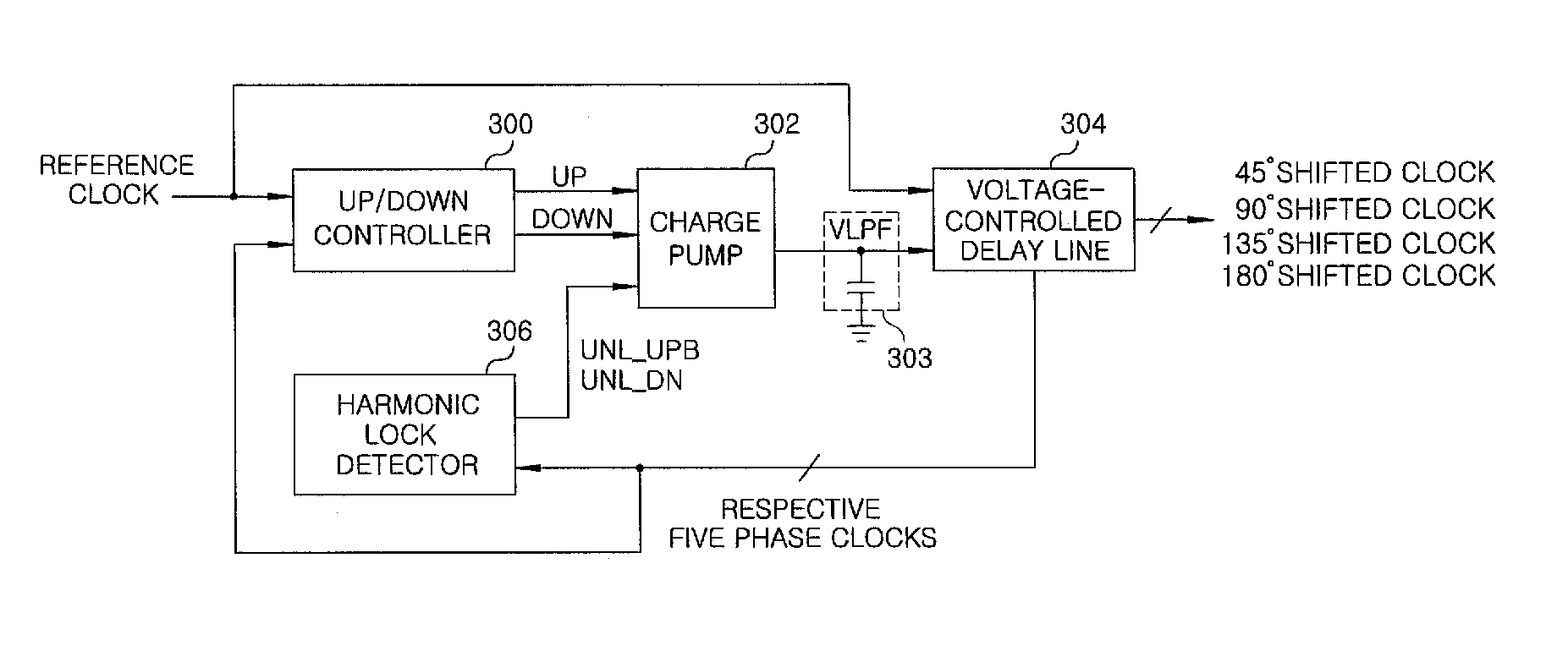
[0011]In general, example embodiments of the invention relate to a delay-locked loop and delay method thereof that provide advantages such as a stable operation at a low frequency. For example, by accurately adjusting the duty ratio of a multi-phase clock to 50:50 and accurately detecting and suppressing harmonic lock of the multi-phase clock, stable operation at a low frequency is provided.
[0013]According to another embodiment, a method for delaying a reference clock with a delay-locked loop includes delaying the reference clock so as to generate a delayed clock, adjusting a delay imposed by the delay line based on a comparison of the reference clock with the delayed clock, and preventing a harmonic lock in the delayed clock such that the delayed clock is locked within a first cycle of the reference clock.
[0014]Accordingly, in the exemplary delay-locked loop and delay method thereof, the duty ratio of the multi-phase clock may be accurately adjusted to 50:50 by using a duty corrector, and harmonic lock of the multi-phase clock may be accurately detected and suppressed. Therefore, a stable operation at a low frequency can be performed, and as a result operation stability of a circuit can be significantly improved.

Problems solved by technology

In the known delay-locked loop, there is a problem in detecting harmonic lock and ensuring a stable operation at a low frequency.
In addition, as a voltage in the voltage-controlled delay line becomes lower, it is difficult to maintain the duty ratio of the output multi-phase clock at 50%.
These problems adversely affect other blocks which utilize the phase, and cause an abnormal operation at a low frequency.

Method used


Image

  • Delay-locked loop for timing control and delay method thereof
  • Delay-locked loop for timing control and delay method thereof
  • Delay-locked loop for timing control and delay method thereof

Examples


Embodiment Construction

[0011]In general, example embodiments of the invention relate to a delay-locked loop and delay method thereof that provide advantages such as a stable operation at a low frequency. For example, by accurately adjusting the duty ratio of a multi-phase clock to 50:50 and accurately detecting and suppressing harmonic lock of the multi-phase clock, stable operation at a low frequency is provided.

[0012]According to one embodiment, a delay-locked loop for timing control includes a voltage-controlled delay line that delays a reference clock to generate a multi-phase clock comprising a plurality of delayed phase clocks; and an up / down controller that receives one of the delayed phase clocks as a feedback clock and generates a frequency up / down control signal based on whether the feedback clock coincides with a falling edge of the reference clock. The delay delay-locked loop for timing control further includes a charge pump that charges or discharges a loop filter connected to the voltage-con...


PUM


Abstract

A delay-locked loop for timing control, includes a voltage-controlled delay line that delays a reference clock to generate a multi-phase clock comprising a plurality of delayed phase clocks; and an up / down controller that receives one of the delayed phase clocks as a feedback clock and generates a frequency up / down control signal based on whether a rising edge of the feedback clock coincides with a falling edge of the reference clock. The delay-locked loop further includes a charge pump that charges or discharges a loop filter connected to the voltage-controlled delay line according to a frequency up / down control signal from the up / down controller; and a harmonic lock detector that compares phases of multiple ones of the delayed phase clocks with a phase of the reference clock, and operates such that the multi-phase clock is locked within a first cycle of the reference clock.

Description

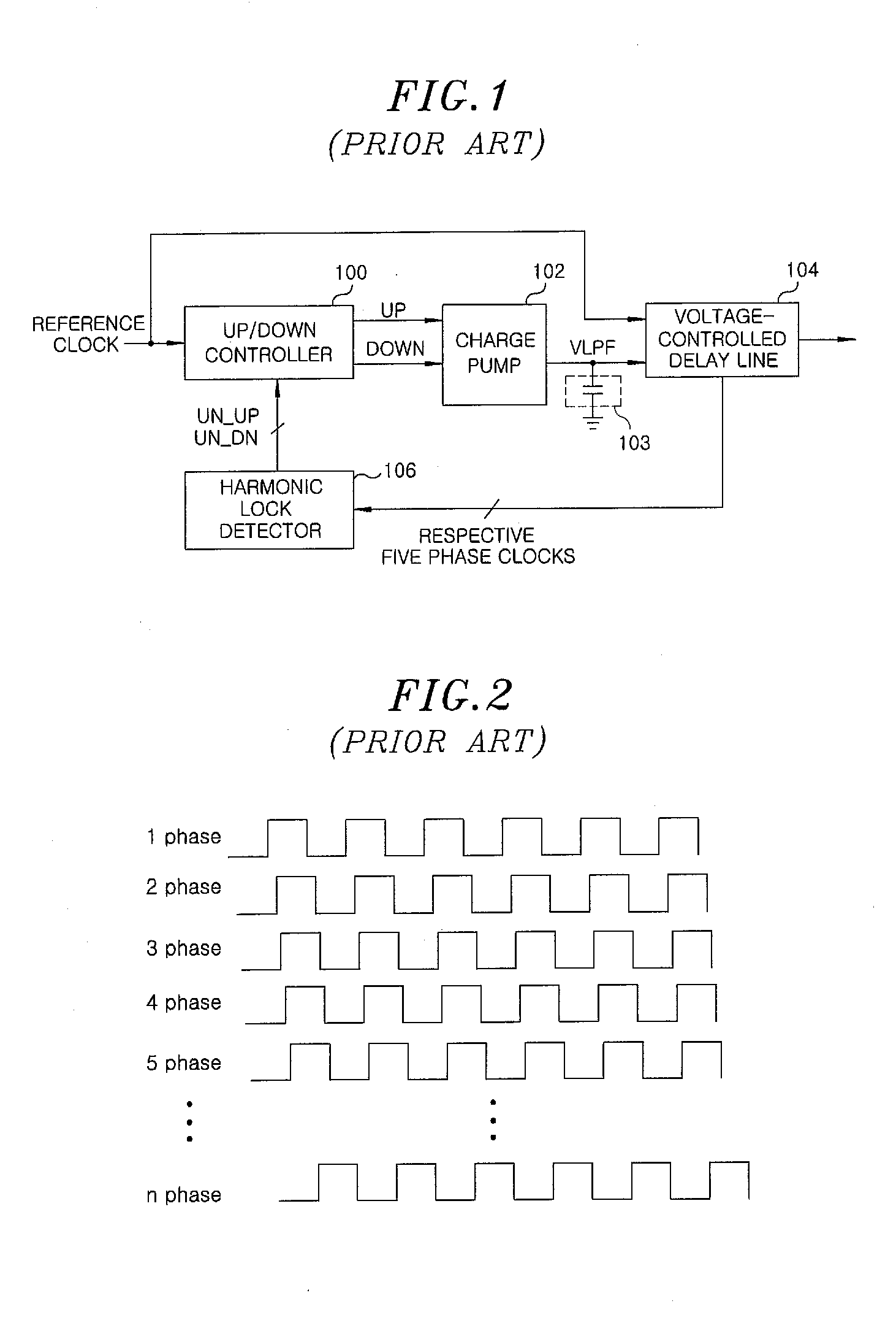
CROSS-REFERENCE TO RELATED APPLICATION[0001]This application claims priority to Korean Application No. 10-2007-0137645, filed on Dec. 26, 2007, which is incorporated herein by reference in its entirety.BACKGROUND[0002]1. Field of the Invention[0003]Embodiments of the present invention relate to a delay-locked loop and delay method thereof that provide, among other advantages, a stable operation at a low frequency.[0004]2. Description of Related Art[0005]In recent years, with an increase in a bandwidth required by systems, a technology that reduces a skew by using a phase-locked loop (PLL) or a delay-locked loop (DLL) has become increasingly important. In particular, the DLL is widely used as a zero delay buffer since it has superior stability and jitter characteristics compared to the PLL.[0006]Such a delay-locked loop delays an input reference clock by an integer cycle and generates a synchronized local clock.[0007]FIG. 1 is a block diagram showing a configuration of a known delay-...

Claims


Application Information

Patent Timeline
IPC IPC(8): H03L7/06
CPCH03L7/0812H03L7/08H03L7/00
Inventor KIM
Owner DONGBU HITEK CO LTD
Learn More